Ford Mustang (1999-2004) Service Manual: Assembly
1. Lubricate all components with the recommended transmission fluid when reassembling.
2. Using the special tools, press the output shaft front bearing on the output shaft.
3. Install the third gear bearing.
- Apply petroleum jelly to the bearing.
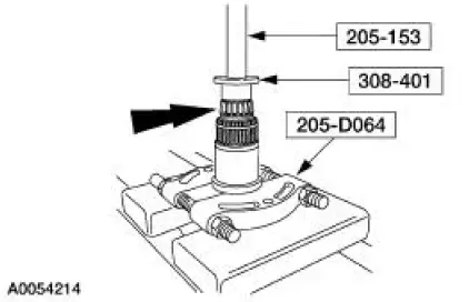
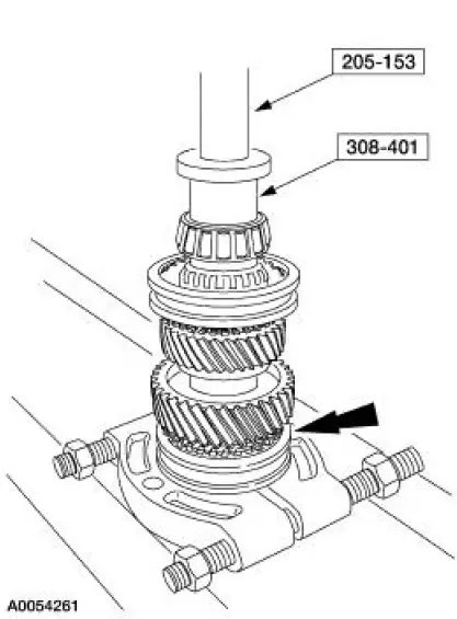
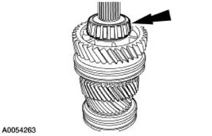
4. Install third gear, the third gear synchronizer blocking ring and the third/fourth gear synchronizer assembly. Position the output shaft with the output end facing upward. Using the special tool, press the third/fourth gear synchronizer assembly into place.
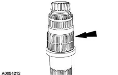
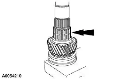
- Install the synchronizer body with the groove facing third gear.
- Stop press operation before keys engage the blocking ring slots. Lift and rotate the third gear and the blocking ring until the keys are seated in the blocking ring.
5. Install a new snap ring.
6. Install the second gear needle bearing.
- Apply petroleum jelly to the bearing.
7. Install second gear.
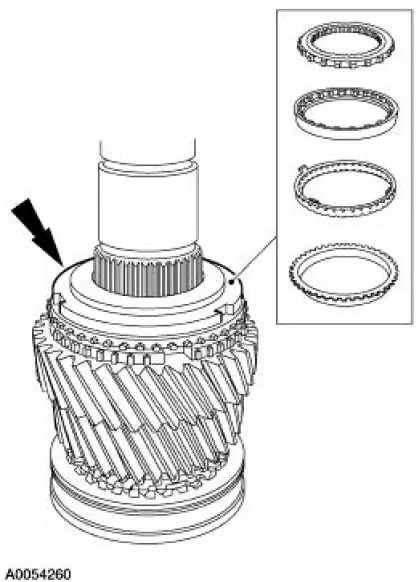
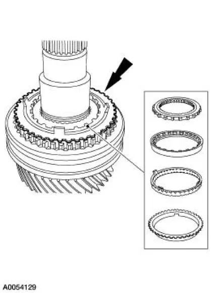
8. Install the second gear synchronizer thrust washer, the inner cone, the friction cone and the second gear synchronizer blocking ring.
- Align the blocking ring tabs with the second gear slots.
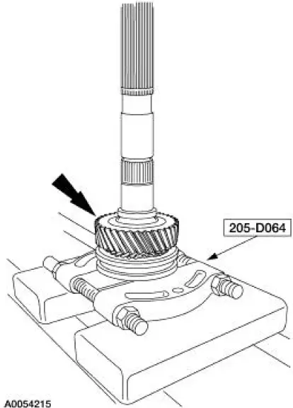
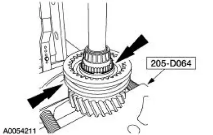
9. Install the first/second gear synchronizer assembly. Position the output shaft with the output end facing downward. Using the special tools, press the first/second gear synchronizer assembly into place.
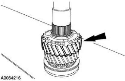
- Install the synchronizer with the groove on the sleeve facing first gear.
- Stop press operation before keys engage the blocking ring slots. Lift and rotate the second gear and the blocking ring until the keys are seated in the blocking ring.
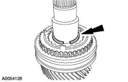
10. Install the first gear synchronizer thrust washer, the inner cone, the friction cone and the first gear synchronizer blocking ring.
11. Install a new snap ring.
12. Install the first gear needle bearing.
- Apply petroleum jelly to the bearing.
13. Install first gear.
- Rotate the gear to align the gear slots with the inner cone tabs.
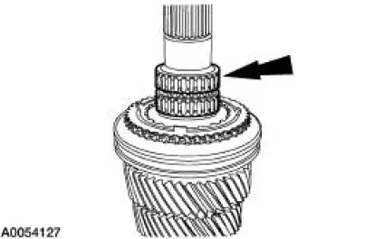
14. Install a new rear output shaft bearing.
15. Using the special tools, install the fifth driven gear.
 Disassembly
1. CAUTION: Hand tighten the special tool to prevent gear damage.
CAUTION: Support the output shaft while using the press to prevent
damage to the
shaft or gears.
Using the special tool and ...
 Countershaft
Special Tool(s)
Plate, Bearing Oil Seal
205-090 (T75L-1165-B)
Puller, Bearing
205-D064 (D84L-1123-A)
Installer, Drive Pinion Bearing
Cone
205-004 (T53T-4621- ...
Other materials:
Interior Trim and Ornamentation
General Specifications
Torque Specifications
Interior Trim
The interior trim consists of:
A-pillar lower trim panels
door trim panels
headliner (coupe)
package tray trim panel (coupe)
quarter trim panels
upper quarter trim panels (coup ...
Weld Nut Repair - "J" Nut, Restraints Control
Module
(RCM)
WARNING: To avoid accidental deployment and possible personal
injury, the backup
power supply must be depleted before repairing or replacing any front or
side air bag
supplemental restraint system (SRS) components and before servicing,
replacing, ...
Crankshaft Rear Seal
Special Tool(s)
Impact Slide Hammer
100-001 (T50T-100-A)
Remover, Crankshaft Rear
Seal
303-519 (T95P-6701-EH)
Replacer, Rear Crankshaft
Seal
303-516 (T95P-6701-BH)
Spacer, Rear Crank Seal
Replacer
30 ...
