Ford Mustang (1999-2004) Service Manual: Assembly
1. NOTE: Universal joint kits are to be installed as complete assemblies only. Do not mix components from other U-joint kits.
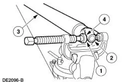
Install the spider.
1. Start a new bearing cup into the driveshaft yoke.
- Check the needle bearings for correct positioning.
2. Position the new spider in the driveshaft yoke.
3. Position the driveshaft in the U-joint tool.
4. Press the bearing cup to just below the snap ring groove.
- Repeat for the other bearing cup.
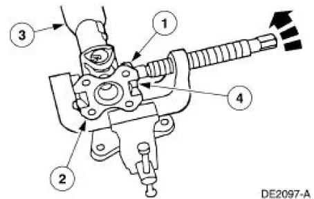
2. Inspect the driveshaft flange yoke. Install new if necessary.
3. Install the driveshaft flange yoke.
1. Start a new bearing cup into the driveshaft flange yoke.
- Check the needle bearings for correct positioning.
2. Position the driveshaft flange yoke.
3. Position the driveshaft in the U-joint tool.
4. Press the bearing cup to just below the snap ring groove.
- Repeat for the other bearing cup.
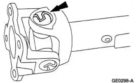
4. NOTE: Use the yellow snap rings supplied in the kit to assemble the universal joint (U-joint). If difficulty is encountered with the yellow snap rings, install the black snap rings, as required.
Remove the driveshaft from the U-joint tool, and install the four snap rings.
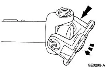
5. NOTE: Do not strike the bearings.
Check the U-joints for freedom of movement.
- If binding, strike the yoke with a brass or plastic hammer.
6. Install the driveshaft. For additional information, refer to Driveshaft in this section.
 Disassembly
1. Remove the driveshaft (4602). For additional information, refer to
Driveshaft in this section.
2. CAUTION: Under no circumstances is the driveshaft assembly to be
clamped in the
jaws of a vise o ...
 Rear Drive Axle/Differential - Ford 7.5-Inch Ring Gear
General Specifications
a: In-vehicle repair refill capacities are determined by filling the rear axle
with the specified lubricant to
6.4-14.3-mm (1/4-9/16-in) below the bottom of the fill hole.
To ...
Other materials:
Parking Brake Control
Removal
1. CAUTION: If any component in the parking brake system requires
repair or if the
rear axle housing (4010) is removed, the cable tension must be released.
Place the parking brake control (2780) in the released position.
2. Remove the console.
3. ...
Installation
1. CAUTION: Do not use metal scrapers, wire brushes, power abrasive
discs or other
abrasive means to clean the sealing surfaces. These tools cause scratches and
gouges
which make leak paths. Use a plastic scraping tool to remove all traces of old
sealant.
...
Fuel Charging and Controls
The fuel injection supply manifold (9F792):
delivers fuel to the fuel injector.
receives fuel from the fuel supply line.
The throttle body:
controls air supply to the upper intake manifold by positioning the
throttle plate.
connects the accelerator ca ...
