Ford Mustang (1999-2004) Service Manual: Disassembly
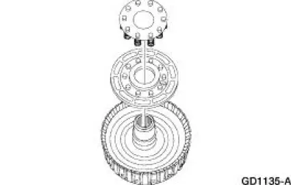
1. NOTE: The index mark on the output shaft must be aligned with the index mark on the output shaft ring gear during the assembly procedure.
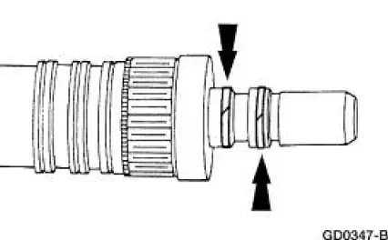
Remove the ring gear snap ring.
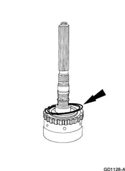
2. Separate the ring gear and output shaft.
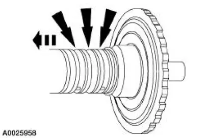
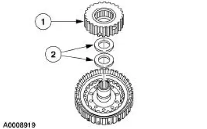
3. Remove the three output shaft seal rings.
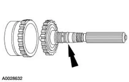
4. Remove the output shaft hub snap ring and the output shaft hub.
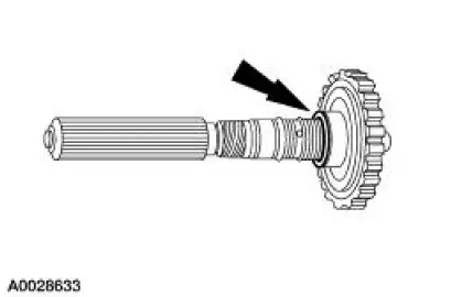
5. Remove the two direct clutch seal rings.
6. Remove the No. 7 direct clutch inner bearing support.
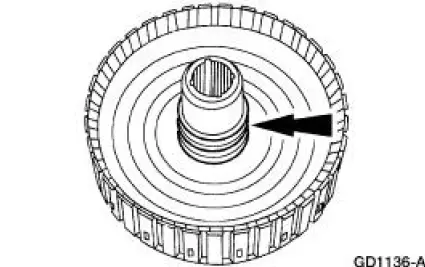
1. Remove the direct clutch hub.
2. Remove the No. 7 direct clutch inner bearing support.
7. Inspect the clutch cylinder thrust surfaces, piston bore and clutch plate serrations for scores or burrs. Minor scores or burrs may be removed with a crocus cloth. Install a new clutch cylinder if badly scored or damaged.
8. Check the fluid passage in the clutch cylinder for obstructions. Clean out all fluid passages.
Inspect the clutch piston for scores and install new if necessary. Inspect the check balls for freedom of movement and correct seating.
9. Check clutch release spring for distortion and cracks. Install a new spring (including wave spring) if distorted or cracked.
10. Inspect composition clutch plates, steel clutch plates and clutch pressure plate for worn or scored bearing surfaces. Install new parts if they are deeply scored or burred.
11. Check the clutch plates for flatness and fit on the clutch hub serrations. Discard any plate that does not slide freely on the serrations or that is not flat.
12. Check the clutch hub thrust surfaces for scores and clutch hub splines for wear.
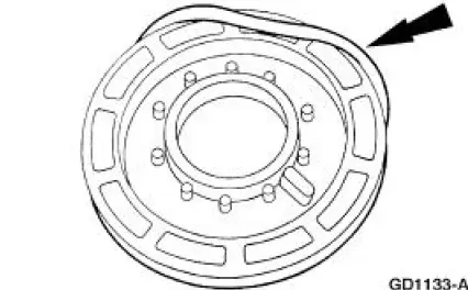
13. Remove the direct clutch pack.
1. Remove the selective retaining ring.
2. Remove the direct clutch pack.
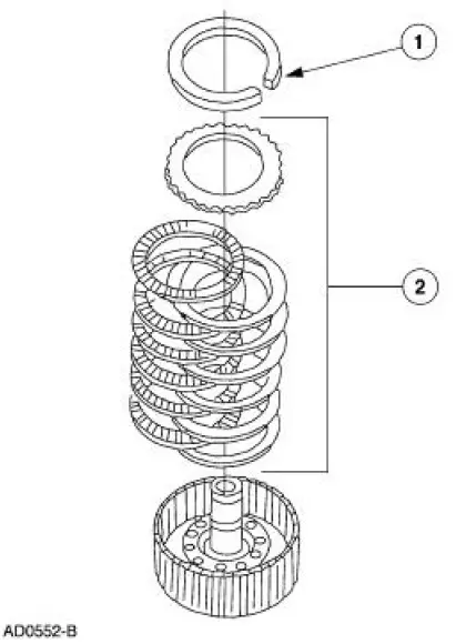
14. Using the special tool, compress the piston return spring and remove the snap ring.
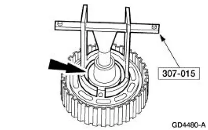
15. WARNING: Wear safety glasses when using compressed air.
NOTE: If necessary, use regulated compressed air 207 kPa (30 psi) max pressure to remove the clutch piston.
Remove the support and spring assembly and piston.
16. Remove the inner piston seal.
17. Remove the outer piston seal.
 Output Shaft and Direct Clutch Cylinder
Special Tool(s)
Compressor, Clutch Spring
307-015 (T65L-77515-A)
Protector, Piston Seal
307-080 (T80L-77234-A)
Protector, Transmission Direct
Clutch Outer Flui ...
 Assembly
1. NOTE: Lubricate direct clutch piston inner seal and seal protector
with petroleum jelly.
Using the special tool, install the inner piston seal.
Install the seal with sealing lip facing down.
...
Other materials:
Anti-Lock Control - Traction Control
Torque Specifications
Anti-Lock Control -Traction Control
The four wheel anti-lock brake system (4WABS) with traction control consists
of the following
components:
anti-lock brake control module (2C346)
front anti-lock brake sensor (2C204)/(2C205)
front ...
Gearshift Lever and Boot
Material
Removal and Installation
1. Remove the gearshift lever knob.
2. Remove the console panel gearshift plate. Lift the gearshift lever boot
over the gearshift lever.
3. Remove the bolts and the shift lever.
4. Remove the screws and the inner shif ...
Using sync with your media player
You can access and play music from your digital music player over
the vehicleŌĆÖs speaker system using the systemŌĆÖs media menu or voice
commands. You can also sort and play your music by specific categories,
such as artists, albums, etc.
SYNC is capable of ...
