Ford Mustang (1999-2004) Service Manual: Disc and Pressure Plate - 3.8L and 4.6L (2V) Engines
Special Tool(s)
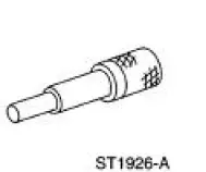 |
Clutch Aligner 308-020 (T74P-7137-K) |
Material
| Item | Specification |
| Premium Long Life Grease XG-1-C | ESA-M1C75-B |
1. Remove the transmission.
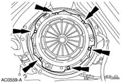
2. CAUTION: Loosen the bolts evenly to prevent clutch pressure plate damage.
NOTE: If the parts are to be reused, mark the clutch pressure plate and the flywheel.
Remove the bolts and remove the clutch pressure plate and the clutch disc.
Installation
NOTE: Clean the clutch pressure plate and flywheel with a commercial alcohol-based solvent so surfaces are free from oil film.
Do not use cleaners with a petroleum base. Do not immerse the clutch pressure plate in the solvent.
1. Position the clutch disc on the flywheel.
- Using the special tool, align the clutch disc.
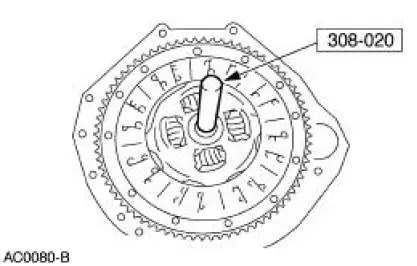
2. NOTE: If reusing the clutch pressure plate, align the plate using the marks made during removal.
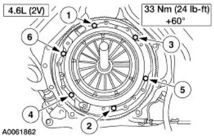
Using the special tool, align the clutch pressure plate and install it on the dowels.
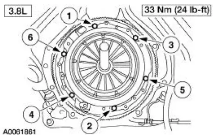
- Install the bolts in the sequence shown.
- Remove the special tool.
3. NOTE: Before installing the transmission, the ball stud, the clutch release lever and the input shaft must be cleaned and lubricated with grease.
Install the transmission.
 Clutch (Description and Operation)
The primary function of the clutch is to couple and uncouple engine power
to the transmission upon
driver command.
The clutch is a single plate, dry friction clutch disc. The clutch
disc ha ...
 Disc and Pressure Plate - 4.6L (4V) Engine
Special Tool(s)
Clutch Aligner
308-020 (T74P-7137-K)
Material
Item
Specification
Premium Long Life Grease
XG-1-C
ESA-M1C75-B
1. Disconnect the battery ground cable. ...
Other materials:
Cable and Conduit - Front
Removal
1. CAUTION: If any component in the parking brake system requires
repair or if the
rear axle housing (4010) is removed, the cable tension must be released.
Release the cable tension. For additional information, refer to Parking
Brake Cable Tens ...
Synchronizers
Disassembly and Assembly
NOTE: This procedure applies to all synchronizer assemblies.
1. NOTE: Synchronizer components are not interchangeable. During
disassembly, mark each
individual synchronizer for assembly. Synchronizer hubs and sleeves are a
selected a ...
Removal
1. Disconnect the battery ground cable. For additional information, refer to
Section.
2. Drain the cooling system. For additional information, refer to Section.
3. Recover the refrigerant. For additional information, refer to Section.
4. Remove the air cle ...
