Ford Mustang (1999-2004) Service Manual: Driveline Angle Inspection
Special Tool(s)
|
|
Anglemaster II Driveline Inclinometer 164-R2402 or equivalent |
NOTE: An incorrect driveline angle can cause a vibration or shudder.
1. Check the vehicle for evidence or overload or sagging. Check for specified air pressures information in all four tires.
2. Normalize the suspension.
3. Drive the vehicle onto a drive-on hoist or back onto a front-end alignment rack.
4. Inspect the suspension and chassis. Verify that the vehicle curb position ride height is within specification.
- Measure the curb position ride height with the vehicle empty and all fluids full.
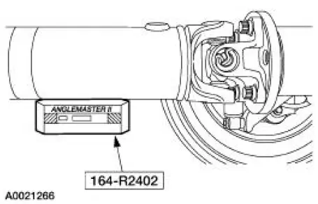
5. Place the Inclinometer flush against the bottom of the driveshaft. After the tool has been held on the driveshaft surface for 5 seconds, push the ALT ZERO button to calibrate to zero degrees.
Remove the tool.
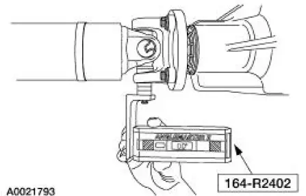
6. To check the pinion angle, rotate the driveshaft so that the rear axle pinion flange yoke ear is parallel to the floor. Remove the U-joint snap ring, then install the special tool. Check and record the pinion angle reading.
- If the angle is not within specification, repair or adjust to obtain the correct angle. Inspect the rear suspension, rear axle, rear axle mounting or the frame for wear or damage.
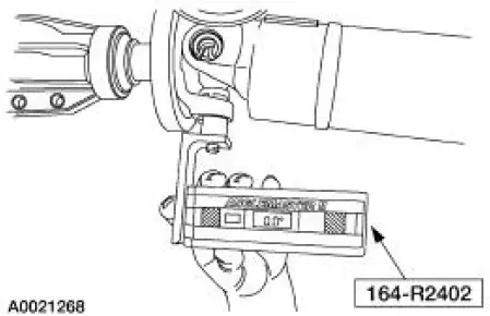
7. To check the engine angle, rotate the driveshaft so that the slip yoke ear is parallel to the floor.
Remove the U-joint snap ring, then install the special tool. Check and record the engine angle reading.
- If the angle is not within specifications, repair or adjust to obtain
the correct angles.
Inspect the powertrain/drivetrain mounts or frame rails for wear or damage.
 Component Tests
Driveline Vibration
An analysis of driveline vibration can also be conducted using the Vibration
Analyzer; follow the
manufacturer's directions.
Driveline vibration exhibits a higher frequency and l ...
 Axle Housing Casting Porosity (Holes in Casting) Repair
CAUTION: To keep the axle's sound characteristics, do not disassemble
the carrier.
NOTE: Casting porosity is a condition where occasionally gas bubbles will
form during the casting
process leaving s ...
Other materials:
Extension Housing Seal and Gasket
Special Tool(s)
Slide Hammer
100-001 (T50T-100-A)
Installer, Transmission
Extension Housing Fluid Seal
308-002 (T61L-7657-A)
Remover, Transmission Fluid
Seal
307-048 (T74P-77248-A)
Removal
1. Drain the transmiss ...
Remote control
Integrated Keyhead Transmitters
The key blade is used to start the
vehicle and unlock or lock the
driver’s door from outside the
vehicle. The transmitter portion
functions as the remote control.
Note: If the vehicle is not equipped with active anti-theft sy ...
Removal
1. CAUTION: The vehicle must be on level ground and at curb height.
Mark the rear shock absorbers relative to their protective sleeve.
During installation, raise the suspension to this reference mark before
tightening the
suspension component fasteners.
...
