Ford Mustang (1999-2004) Service Manual: Spring Lock Coupling
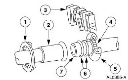
The spring lock coupling is a refrigerant line coupling held together by a garter spring inside a circular cage.
- When the coupling is connected together, the flared end of the female fitting slips behind the garter spring inside the cage of the male fitting.
- The garter spring and cage then prevent the flared end of the female fitting from pulling out of the cage.
- Three O-ring seals are used to seal between the two halves of the A/C condenser core couplings. All other couplings have two O-ring seals.
- Use only the O-ring seals listed in the Ford Master Parts Catalog for the spring lock coupling.
- A plastic indicator ring is used on the spring lock couplings of the A/C evaporator core to indicate, during vehicle assembly, that the coupling is connected. Once the coupling is connected, the indicator ring is no longer necessary but will remain captive by the coupling near the cage opening.
- The indicator ring may also be used during repair operations to indicate connection of the coupling.
- An A/C tube lock coupling clip (19E746) may be used to secure the coupling but is not required.
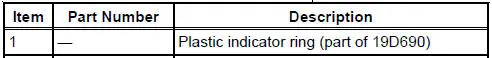
Service Gauge Port Valves
The high-pressure service gauge port valve is located on the A/C manifold and tube.
The low pressure service gauge port valve is located on the suction accumulator.
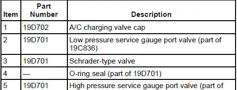
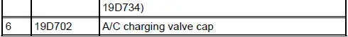
The fitting is an integral part of the refrigeration line or component.
- Special couplings are required for both the high side and low side service gauge ports.
- A new Schrader-type valve core can be installed if the seal leaks.
- Always install the A/C charging valve cap (19D702) on the service gauge port valves after repairing the refrigerant system.
 Dual-Function Pressure Switch (4.6L)
The dual-function pressure switch is used to interrupt A/C compressor
operation in the event of high system discharge pressures.
The dual-function pressure switch is mounted on a Schrader valve-t ...
 Air Conditioning (A/C) Compressor - 3.8L
Material
Item
Specification
PAG Refrigerant Compressor
Oil (R-134a Systems)
F7AZ-19589-DA (Motorcraft YN-
12-C)
WSH-M1C231-
B
Removal and Installation
CAUTION: If installing ...
Other materials:
Manual Transaxle/Transmission - TR3650
General Specifications
Torque Specifications
...
Valve Spring Strength
Special Tool(s)
Pressure Gauge, Valve/Clutch
Spring
303-006 (TOOL-6513-DD) or
equivalent
1. Use a Valve/Clutch Spring Pressure Gauge to check the valve spring for
correct strength at the
specified valve spring length.
Refer to the appr ...
Differential Housing Cover
Removal
1. Raise and support the vehicle.
2. NOTE: Empty the lubricant into a clean container for reuse.
Remove the differential housing cover (4033).
1. Remove the 10 bolts and drain the lubricant from the differential
housing (4010).
2. Remove the d ...
