Ford Mustang (1999-2004) Service Manual: Engine (Disassembly)
Special Tool(s)
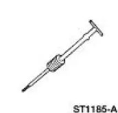 |
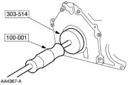
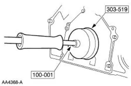
Impact Slide Hammer 100-001 (T50T-100-A) |
 |
Remover, Crankshaft Rear Oil Slinger 303-514 (T95P-6701-AH) |
 |
Remover, Crankshaft Rear Oil Seal 303-519 (T95P-6701-EH) |
 |
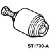
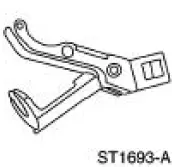
Remover, Crankshaft Vibration Damper 303-009 (T58P-6316-D) |
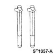 |
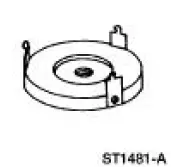
Installer, Connecting Rod 303-442 (T93P-6136-A) |
 |
Remover, Crankshaft Front Oil Seal 303-107 (T74P-6700-A) |
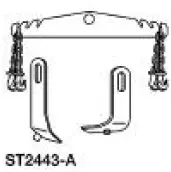 |
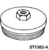
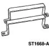
Engine Lift Bracket Set 303-DS086- (D93P-6001-EA) |
 |
Cylinder Ridge Reamer 303-016 (T64L-6011-EA) |
 |
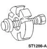
Compressor, Valve Spring (Exhaust) 303-567 (T97L-6565-AH) |
 |
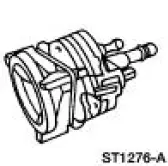
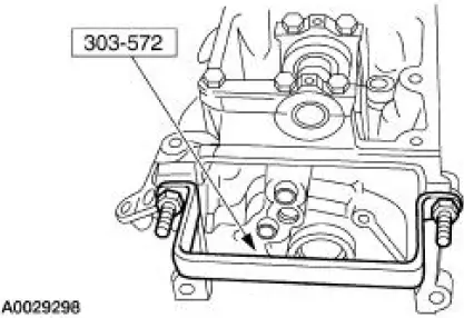
Remover/Installer, Cylinder Head 303-572 (T97T-6000-A) |
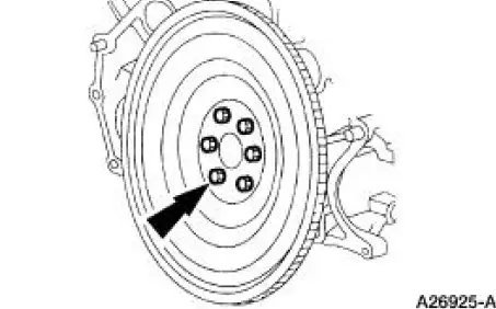
1. Remove the flywheel.
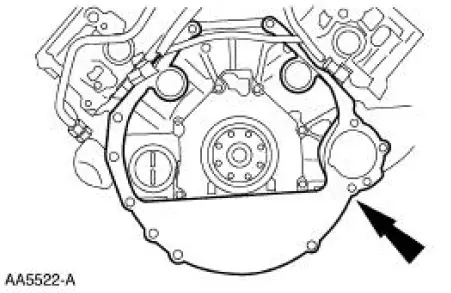
2. Remove the separator plate.
3. Using the special tools, remove the crankshaft rear oil slinger.
4. Using the special tools, remove the rear main seal.
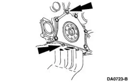
5. Remove the rear seal retainer plate.
6. Mount the engine on a work stand.
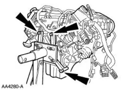
7. NOTE: RH shown, LH similar.
Remove the RH and LH lifting eyes.
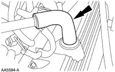
8. Remove the breather tube.
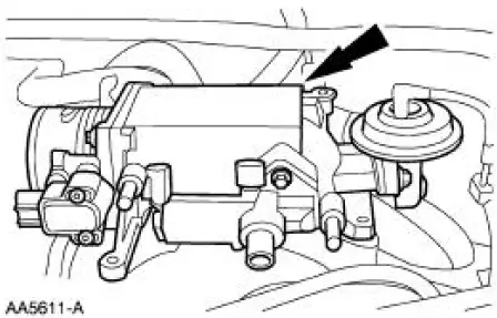
9. Disconnect the differential pressure feedback EGR electrical connector.
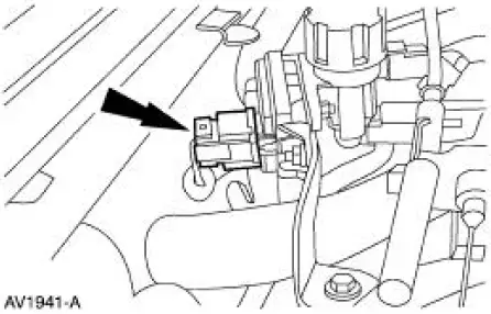
10. Disconnect the hoses from the differential pressure feedback EGR transducer (9J434).
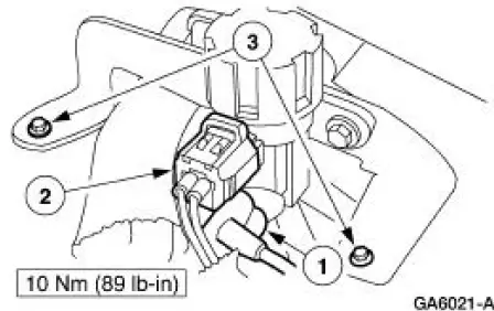
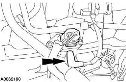
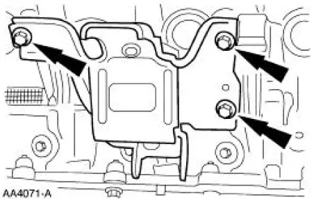
11. Remove the EGR vacuum regulator solenoid.
1. Remove the vacuum hoses.
2. Remove the electrical connector.
3. Remove the bolts.
12. Disconnect the exhaust gas recirculation (EGR) tube from the EGR valve.
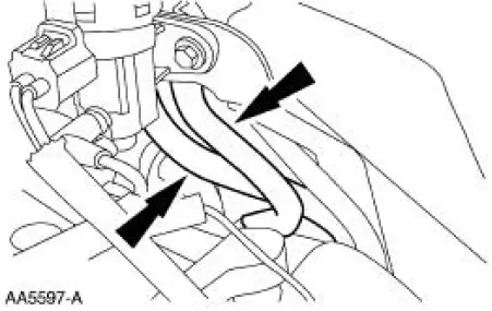
13. Disconnect the positive crankcase ventilation (PCV) hose from the base of the throttle body.
14. Disconnect the PCV valve hose.
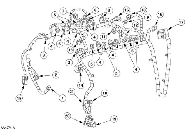
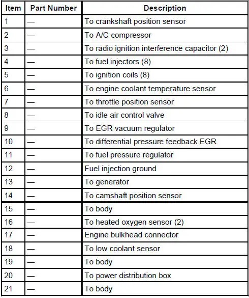
15. Remove the engine wiring harness.
16. Disconnect the vacuum line to the fuel pressure sensor.
17. Remove the throttle body bolts.
18. NOTE: The gasket is reusable if not damaged.
Remove the throttle body and adapter as an assembly.
- Inspect and clean the sealing surfaces.
19. Remove the ignition coils.
20. Remove the radio interference capacitors.
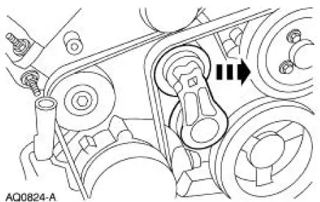
21. Rotate the belt tensioner and remove the accessory drive belt.
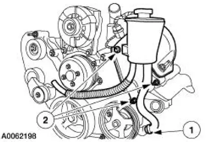
22. Remove the power steering reservoir bracket as an assembly.
1. Disconnect the supply line from the pump.
2. Remove the three bolts and reservoir.
23. Remove the upper generator support bracket.
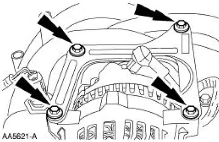
24. Remove the bolts and the generator.
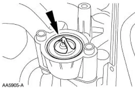
25. Remove the water outlet connector.
26. Remove the water thermostat and O-ring.
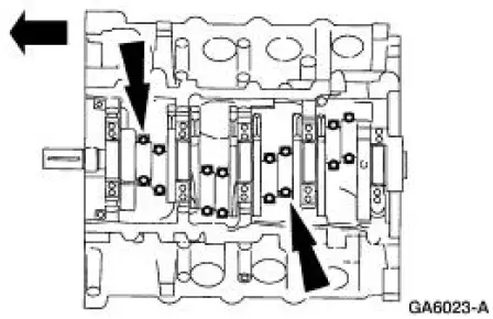
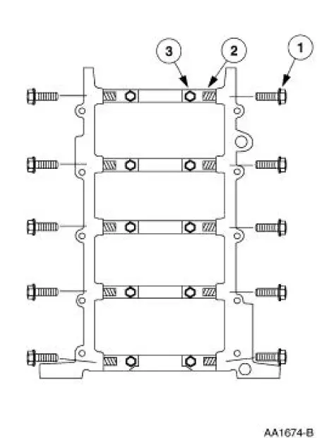
27. Remove the bolts in the sequence shown, and remove the intake manifold.
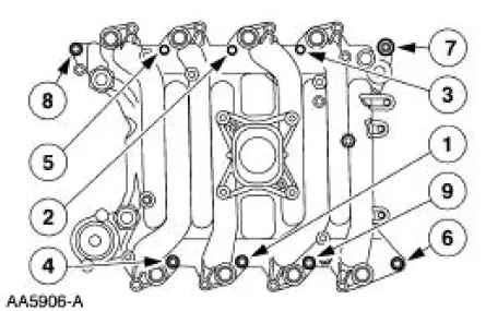
28. Remove the intake manifold gaskets.
29. CAUTION: Do not use metal scrapers, wire brushes, power abrasive discs or other means to clean sealing surfaces. These tools cause scratches and gouges which make leak paths.
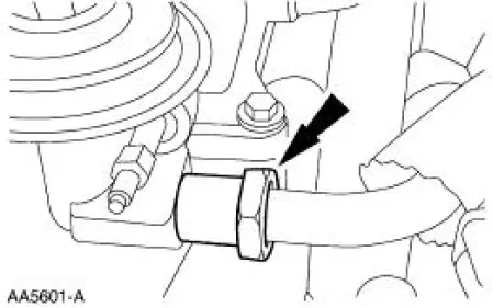
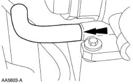
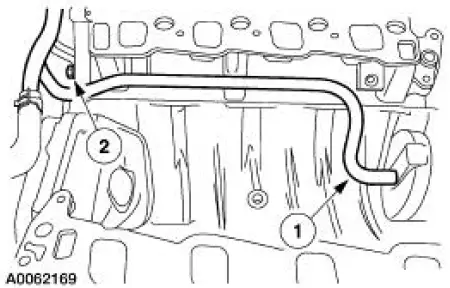
Remove the water bypass tube.
1. Remove the nut.
2. Remove the water bypass tube.
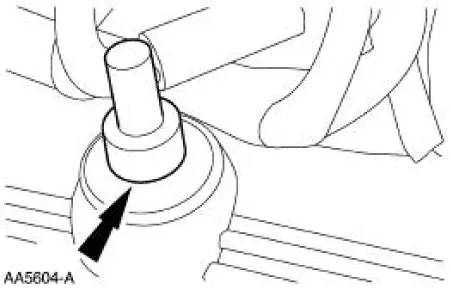
30. NOTE: RH shown, LH similar.
Remove the RH and the LH engine mount.
31. NOTE: One side shown, other side similar.
Using a suitable container, drain coolant from the engine block.
- Install the drain plugs when finished.
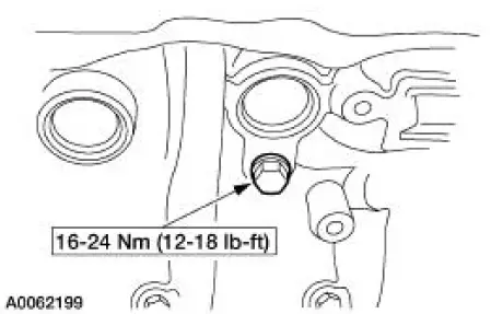
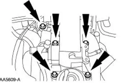
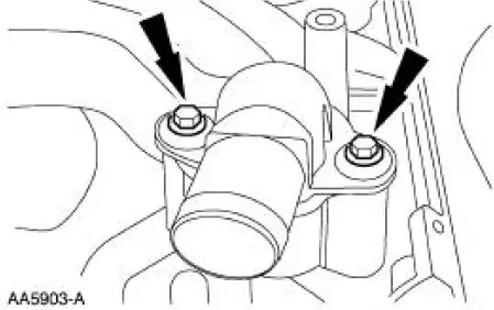
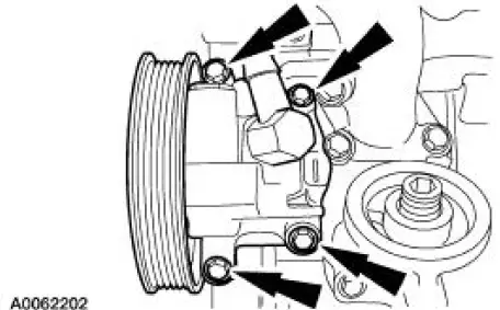
32. Remove the four bolts and the power steering pump.
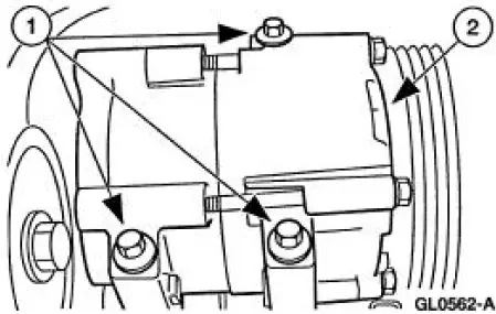
33. Remove the compressor.
1. Remove the bolts.
2. Remove the compressor.
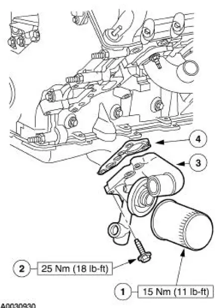
34. Remove the oil filter adapter.
1. Remove the oil bypass filter.
2. Remove the bolts.
3. Remove the oil filter adapter.
4. Clean and inspect the sealing surfaces.
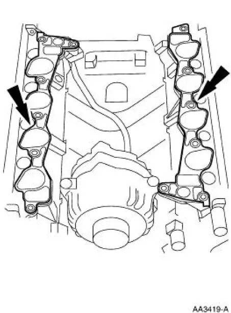
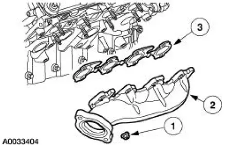
35. Remove the LH exhaust manifold.
1. Remove the exhaust manifold nuts.
2. Remove the exhaust manifold.
3. Remove the exhaust manifold gasket and discard.
36. Disconnect the exhaust recirculation (EGR) tube (9D477) at the exhaust manifold.
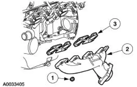
37. Remove the RH exhaust manifold.
1. Remove the exhaust manifold nuts.
2. Remove the exhaust manifold.
3. Remove the exhaust manifold gasket and discard.
38. Clean and inspect the exhaust manifolds. For additional information, refer to Section.
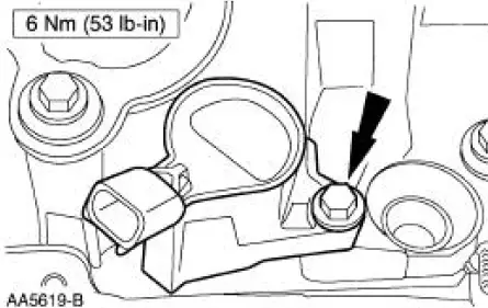
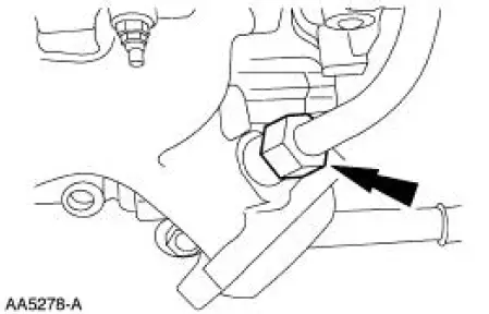
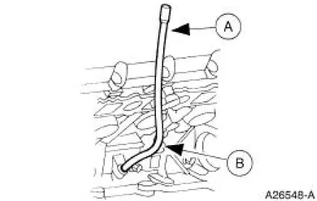
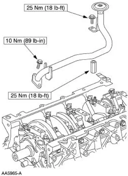
39. Remove the oil level indicator tube bolt.
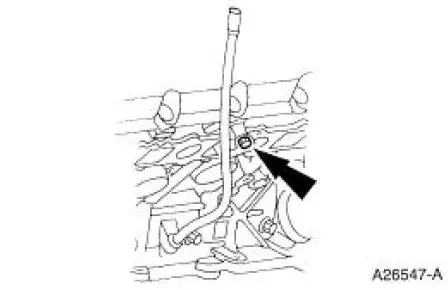
40. Remove the bolt and the oil level indicator tube.
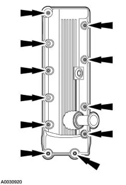
41. Remove valve cover.
- Remove the fasteners.
- Remove the valve cover.
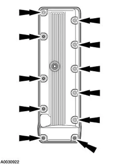
42. Remove valve cover.
- Remove the fasteners.
- Remove the valve cover.
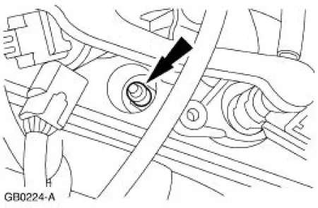
43. NOTE: Use compressed air to remove any foreign material from the spark plug well before removing the spark plugs (12405).
NOTE: One spark plug is shown; others are similar.
Remove the spark plugs.
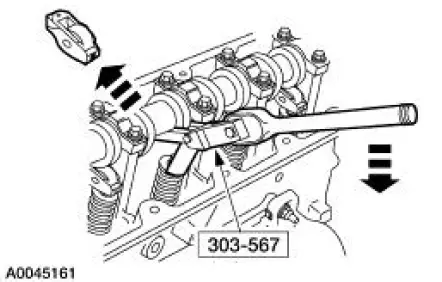
44. NOTE: Rotate the camshaft to the base circle of the camshaft lobe before removing followers.
Keep roller followers in order when removing.
Use special tool to compress the valve springs (6513) and remove the 16 camshaft roller followers.
- Rotate the camshaft and the crankshaft as necessary.
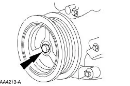
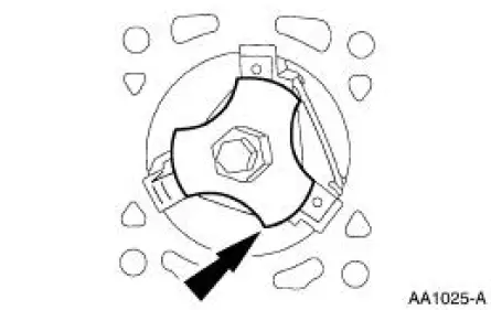
45. Remove the crankshaft pulley bolt.
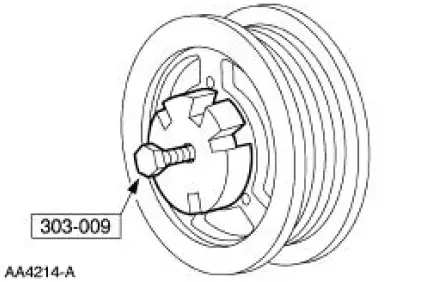
46. Using the special tool, remove the crankshaft pulley.
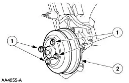
47. Remove the water pump pulley.
1. Remove the water pump pulley bolts.
2. Remove the water pump pulley.
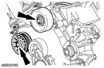
48. Remove the bolts and belt idler pulleys.
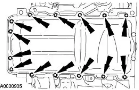
49. NOTE: The gasket can be reused if not damaged.
Remove the oil pan.
- Remove the bolts.
- Remove the oil pan.
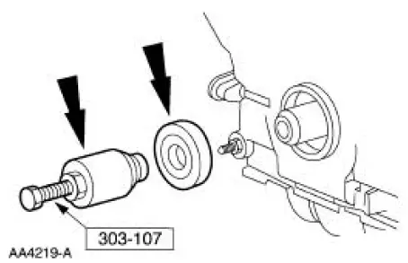
50. Using the special tool, remove the front cover seal.
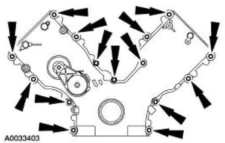
51. Remove the bolts, the studs, and the engine front cover.
- Discard the gaskets. Clean and inspect the sealing surfaces.
CAUTION: Since the engine is not free-wheeling, if the crankshaft or the camshafts are moved in any manner during removal and installation, the crankshaft and the camshafts must be re-synchronized.
52. Remove the crankshaft sensor ring from the crankshaft.
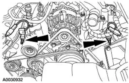
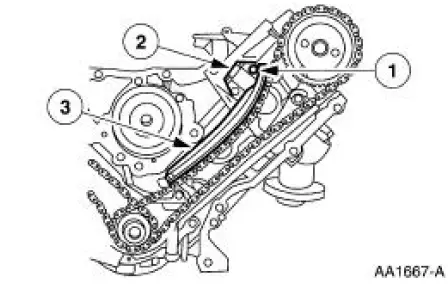
53. Remove the RH and LH timing chain tensioner (RH shown, LH similar).
1. Remove the bolts.
2. Remove the timing chain tensioners.
3. Remove the timing chain tensioner arms.
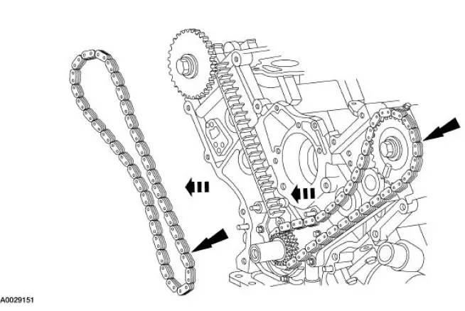
54. CAUTION: Unless otherwise instructed, at no time when the timing chains are removed and the cylinder heads are installed is the crankshaft or the camshaft to be rotated. Severe piston and valve damage can occur.
CAUTION: Do not remove the special tool from the camshafts.
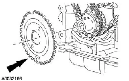
Remove the LH and RH timing chains and the crankshaft sprocket.
- Remove the RH timing chain from the camshaft sprocket.
- Remove the RH timing chain from the crankshaft sprocket.
- Remove the LH timing chain from the camshaft sprocket.
- Remove the LH timing chain from the crankshaft sprocket.
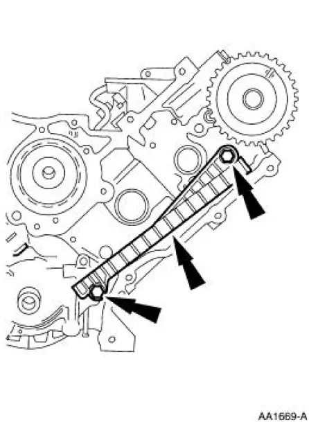
55. NOTE: The LH is shown and the RH is similar.
Remove the bolts and the timing chain guides.
56. NOTE: One side shown, other side similar.
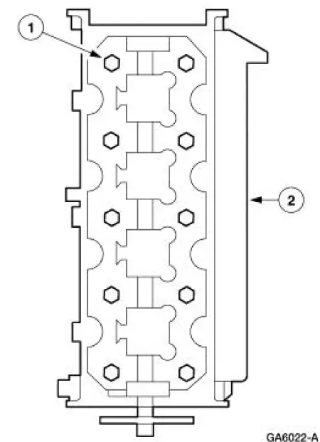
Install the lifting handles to the RH and LH cylinder heads.
57. CAUTION: New cylinder head bolts must be installed. They are tighten-to-yield designed and cannot be reused.
CAUTION: Place cylinder head on cardboard or wood surface to prevent damage to the joint face.
Remove the RH and LH cylinder heads.
1. Remove the bolts.
2. Remove the cylinder heads.
58. CAUTION: Do not use metal scrappers, wire brushes, power abrasive discs or other abrasive means to clean gasket surfaces. These tools cause scratches and gouges that make leak paths. Use a plastic scrapping tool to remove all traces of the head gasket (6051).
Clean and inspect all of the sealing surfaces. For additional information, refer to Section.
59. Remove the oil pump screen cover and tube, and the spacer.
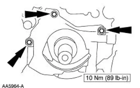
60. Remove the oil pump.
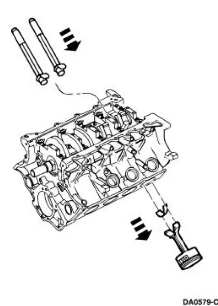
61. CAUTION: Do not stamp the top of pistons, as ring land damage can occur.
NOTE: Connecting rods and rod caps should be numbered to retain correct orientation.
Remove the connecting rod caps for piston numbers 1 and 6.
- Discard the bolts.
62. CAUTION: Do not scratch cylinder walls or crankshaft journals with the connecting rod.
NOTE: Before removing pistons, inspect the top of the cylinder bores. If necessary, remove the ridge or carbon deposits from each cylinder using a cylinder ridge reamer following the manufacturer's instructions.
Remove the piston removing pistons number 1 and 6 through the top of the cylinder block.
63. Repeat the previous two steps to remove the remaining pistons, rotating the crankshaft 90 degrees between piston pairs 3 and 5, 4 and 7, 2 and 8.
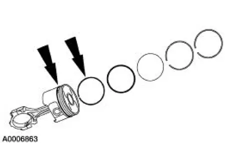
64. Remove the piston rings.
65. Clean and inspect pistons. For additional information, refer to Section.
66. Remove the crankshaft bearing cap fasteners.
1. Remove and discard the cross-mounted main cap bolts.
2. Loosen the jackscrews.
3. Remove and discard the main cap bolts.
67. Remove the main bearing cap and the crankshaft main bearings from the cylinder block.
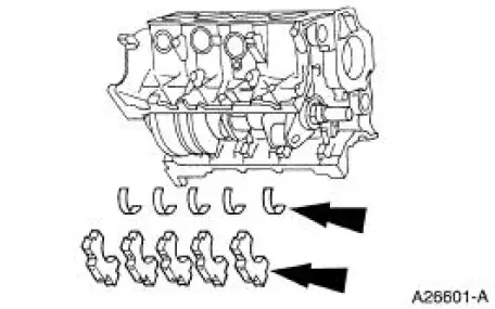
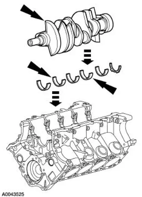
68. Remove the crankshaft, crankshaft main bearings and the thrust washer.
 Engine (Removal)
Special Tool(s)
Special Tool(s)
Support Bracket, Engine
303-639
Spreader Bar
303-D089 (D93P-6001-A3)
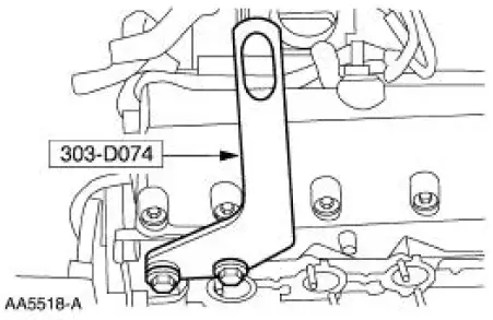
Lifting Bracket Set, Engine
303-D074 (D91P-6001-A)
Re ...
 Cylinder Head (Disassembly and Assembly of Subassemblies)
Special Tool(s)
Compressor, Valve Spring
303-381(T91P-6565-A)
Compressor Spacer, Valve
Spring
303-382 (T91P-6565-AH)
Installer, Valve Stem Oil Seal
303-383 ( ...
Other materials:
Removal
CAUTION: Suspension fasteners are critical parts because they affect
performance of vital
components and systems and their failure can result in major service expense. A
new part with
the same part number must be installed if installation becomes necessary. ...
Engine - 4.6L (2V)
General Specifications
a - With installation of a new filter.
b - Distance front edge of bearing is installed below front face of cylinder
block.
c - Time necessary for plunger to leak down 1.6 mm of travel with 222 N force
and leak down fluid in
tap ...
Refrigerant System Filtering Following Air Conditioning (A/C) Component
Installation
Special Tool(s)
Set, A/C Fittings
412-DS028 (014-00333, D93L-
19703-B) or equivalent
1. Install the new A/C compressor. For additional information, refer to
Section.
2. Install the new suction accumulator/drier. For additional information, ...
