Ford Mustang (1999-2004) Service Manual: Fuel Injectors
Removal
WARNING: Do not smoke or carry lighted tobacco or open flame of any type when working on or near any fuel related components. Highly flammable mixtures are always present and can ignite. Failure to follow these instructions can result in personal injury.
WARNING: Fuel in the fuel system remains under high pressure even when the engine is not running. Before working on or disconnecting any of the fuel lines or fuel system components, the fuel system pressure must be relieved. Failure to follow these instructions can result in personal injury.
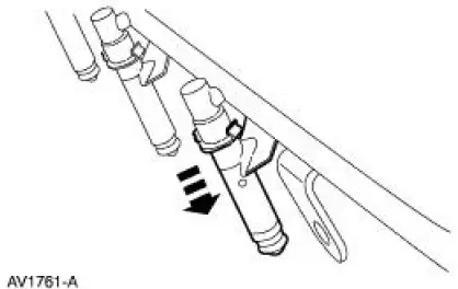
1. Remove the supply manifold. For additional information, refer to Supply Manifold in this section.
2. Remove the eight fuel injectors from the supply manifold.
Installation
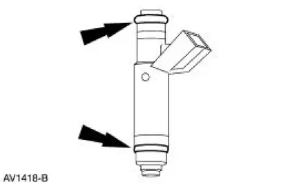
CAUTION: The retaining clip must be in the upper groove on the injector or the injector can become loose.
1. NOTE: Inspect the two O-rings from each fuel injector. Install new O-rings as needed.
NOTE: Lubricate the new O-rings with clean engine oil.
To install, reverse the removal procedure.
 Throttle Body
Removal
WARNING: Do not smoke or carry lighted tobacco or open flame of any
type when
working on or near any fuel related components. Highly flammable mixtures are
always present
and can ignite. Fai ...
 Wiring Harness
...
Other materials:
Moulding - Roof Side
Removal and Installation
1. Remove the weatherstrip.
2. Remove the exterior roof side moulding screws.
3. Remove the interior roof side moulding screws.
4. Remove the roof side moulding screw.
5. Release the clips.
1. Lift up to release the two ...
Symptom Charts
Symptom Chart - Air Leak and Wind Noise
Condition
Possible Sources
Action
Air leak around
door perimeter
Loose fit seal.
Seal installed
incorrectly.
Door misaligned.
Scuff plate installed
incor ...
Installation
1. CAUTION: The timing chain procedures must be followed exactly or
damage to the
valve and pistons will result.
Compress the tensioner plunger, using an edge of a vise.
2. While holding the ratchet mechanism, push the ratchet arm back into the
tensioner ...
