
Ford Mustang (1999-2004) Service Manual: Exhaust Manifold RH
Special Tool(s)
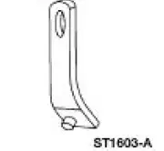 |
Lifting Bracket, Engine 303-D088 (D93P-6001-A2) |
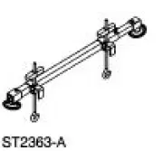 |
Support Bar, Engine 303-290-A |
Removal and Installation
1. Install the special tool.
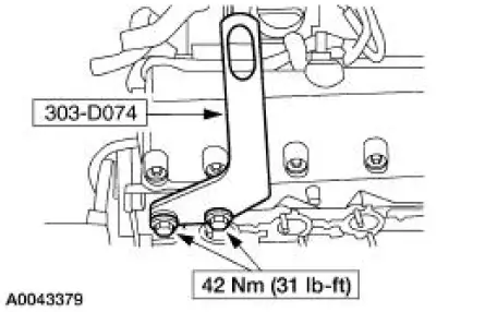
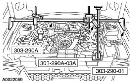
2. Install the special tools.
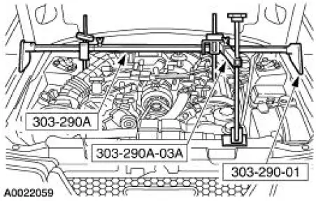
3. Raise and support the vehicle. For additional information, refer to Section.
4. Remove the LH and RH side engine mount nuts.
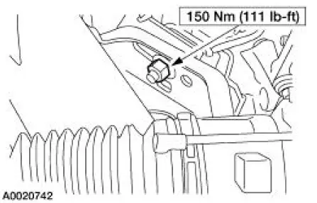
5. Lower the vehicle.
6. Using the special tools, raise the engine.
7. Remove the air cleaner outlet tube. For additional information, refer to Section.
8. Raise and support the vehicle.
9. Remove the starter motor. For additional information, refer to Section.
10. Separate the exhaust at the exhaust manifold. For additional information, refer to Section.
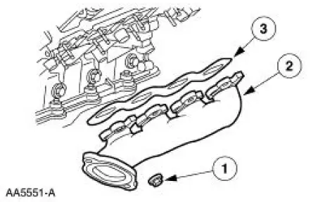
11. Remove the exhaust manifold.
1. Remove the exhaust manifold nuts.
2. Remove the exhaust manifold.
3. Remove the exhaust manifold gasket and discard.
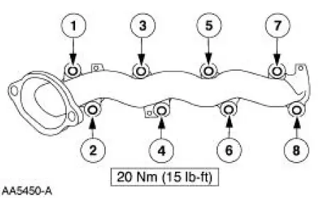
12. NOTE: Tighten the exhaust manifold nuts in the sequence shown.
To install, reverse the removal procedure.
 Camshaft
Removal and Installation
1. Remove the timing chains. For additional information, refer to Timing
Drive Components in this
section.
2. Remove the roller followers. For additional information, refer ...
 Exhaust Manifold LH
Special Tool(s)
Lifting Bracket, Engine
303-D088 (D93P-6001-A2)
Support Bar, Engine
303-290-A
Removal and Installation
1. Install the special tool.
2. Install the speci ...
Other materials:
Fluid Pan, Gasket and Filter
Material
Item
Specification
MERCON V Automatic
Transmission Fluid
XT-5-QM, XT-5-DM
MERCON V
1. Normal maintenance requires periodic automatic transmission fluid changes.
If a major repair,
such as a clutch, band, bearing, etc., is requir ...
Axle Housing Casting Porosity (Holes in Casting) Repair
CAUTION: To keep the axle's sound characteristics, do not disassemble
the carrier.
NOTE: Casting porosity is a condition where occasionally gas bubbles will
form during the casting
process leaving small pockets in the metal that will cause the axle housing t ...
Installation
1. CAUTION: In order to prevent foreign material from contaminating
the engine block
or the engine front cover it is necessary to seal the coolant and oil
passages of both
components. Failure to follow these directions will result in engine damage.
CAU ...
