Ford Mustang (1999-2004) Service Manual: Front Bumper Cover
Removal and Installation
NOTE: Mustang shown, GT and Cobra similar.
1. Remove the pin-type retainers and the radiator upper sight shield.
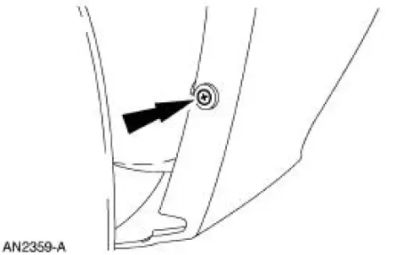
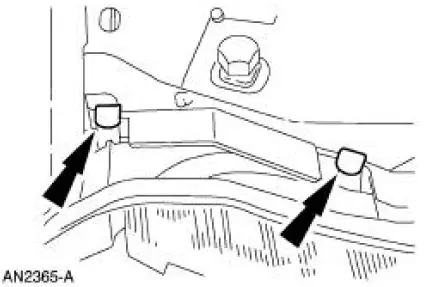
2. Remove the two pin-type retainers (one each side).
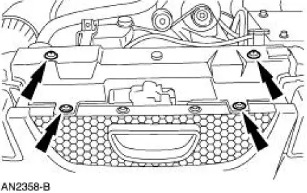
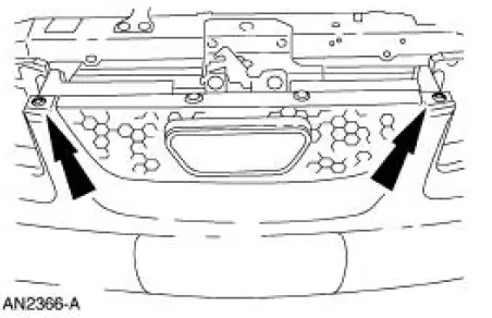
3. Remove the four front bumper cover nuts (two each side).
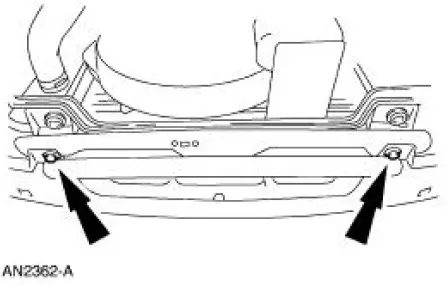
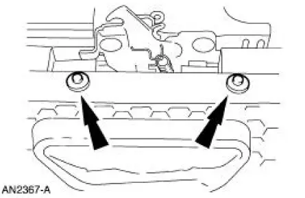
4. Remove the lower bumper cover pin-type retainers.
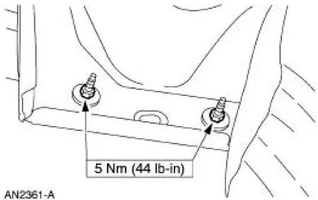
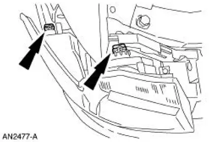
5. Remove the four headlamp mounting clips.
6. Disconnect the parking lamp and the headlamp electrical connectors (two each) and remove the two headlamps.
7. Remove the pin-type retainers.
8. If equipped, remove the pin-type retainers.
9. If equipped, disconnect the fog lamp electrical connectors.
10. Lift up on the tabs and remove the front bumper cover.
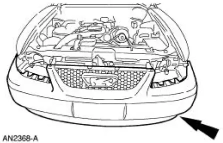
11. To install, reverse the removal procedure.
 Bumpers
Torque Specifications
Bumpers
CAUTION: Never apply excessive heat to the bumper cover surface. Heat
could cause
distortion of the bumper cover.
The bumper systems consist of the following components ...
 Rear Bumper Cover
Removal and Installation
1. Remove the luggage compartment trim panel covers.
2. Remove the seven rear bumper cover nuts.
3. Remove the fuel drain hose.
4. Remove the four bumper cover screws (tw ...
Other materials:
Removal
Automatic transmission vehicles
1. Remove the flexplate. For additional information, refer to Flexplate in
this section.
Manual transmission vehicles
2. Remove the flywheel. For additional information, refer to Flywheel in this
section.
All vehicles
3. Using ...
Disassembly
1. WARNING: To avoid risk of serious personal injury, follow all
warnings, cautions,
notes and instructions in the driver air bag removal and installation procedure.
Remove the steering column (3C529). For additional information, refer to Column
in this
s ...
General Maintenance Information
NOTE: This is a generic maintenance schedule for all Ford, Lincoln and
Mercury vehicles. There may
be items listed that do not apply to all vehicles.
The Normal Schedule applies to operation of the vehicle under typical, everyday
driving conditions.
The ma ...
