Ford Mustang (1999-2004) Service Manual: Fuel Line Fittings - Push Connect
Special Tool(s)
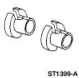 |
Disconnect Tool, Spring Lock Coupling 310-S039 (T90T-9550-S) |
Material
| Item | Specification |
| SAE 5W-20 Super Premium Blend Motor Oil XO-5W20-QSP or equivalent | WSS-M2C153- H |
Disconnect
WARNING: Do not smoke or carry lighted tobacco or open flame of any type when working on or near any fuel-related components. Highly flammable mixtures are always present and may be ignited, resulting in possible personal injury.
WARNING: Fuel in the fuel system remains under high pressure even when the engine is not running. Before servicing or disconnecting any of the fuel lines or fuel system components, the fuel system pressure must be relieved to prevent accidental spraying of fuel, causing personal injury or a fire hazard.
1. Relieve the fuel system pressure. For additional information, refer to Pressure Relief in this section.
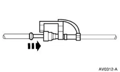
2. Disconnect the safety clip from the male hose.
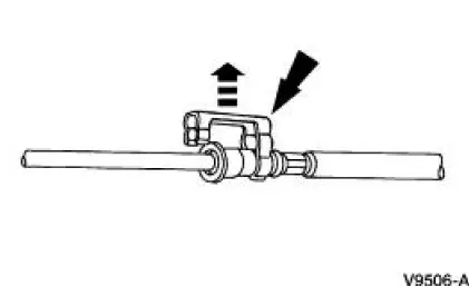
3. Install the Fuel Line Disconnect Set and push into the fitting.
4. Separate the fittings.
- Clean and inspect the fittings for damage.
Connect
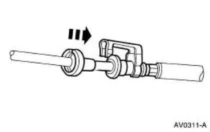
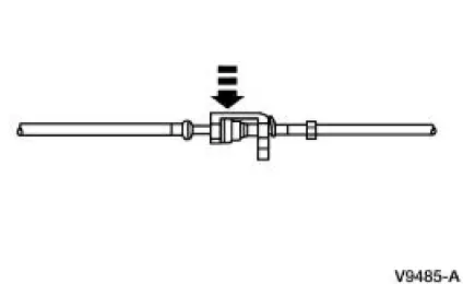
1. NOTE: Lubricate the tube end with clean engine oil to ease assembly.
Connect the fitting.
- Align the tube to the fitting and push until you hear a click.
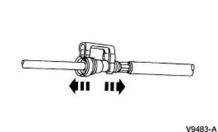
2. Pull on the fitting to make sure it is fully engaged, then install the safety clip.
 Spring Lock Couplings
Special Tool(s)
Disconnect Tool, Spring Lock
Coupling (3/8 inch yellow)
310-D004 (D87L-9280-A) or
equivalent
Disconnect Tool, Spring Lock
Coupling (1/2 inch green)
310 ...
 Fittings - R-Clip
Material
Item
Specification
SAE 5W-20 Super Premium
Synthetic Blend Motor Oil
XO-5W20-QSP or equivalent
WSS-M2C153-
H
Disconnect
WARNING: Do not smoke or carry lighted tobacco ...
Other materials:
Connect
1. Install the A/C tube lock coupling spring.
2. Lubricate the inside of the coupling with PAG Refrigerant Compressor Oil
(R-134a Systems) or
equivalent.
3. CAUTION: Use only the new O-ring seals. The use of any O-ring seals
other than
those specified in ...
Toe Adjustment - Rear
1. Loosen the nuts.
To prevent damage to the ball joints, hold the tie-rod ends while
loosening the nuts.
2. Rotate the toe link to the correct toe setting.
3. Tighten the nuts.
To prevent damage to the ball joints, hold the tie-rod ends wh ...
Glass, Frames and Mechanisms
WINDOW REGULATOR ELECTRIC DRIVE
CURRENT DRAW
General Specifications
Torque Specifications
...
