Ford Mustang (1999-2004) Service Manual: Spring Lock Couplings
Special Tool(s)
 |
Disconnect Tool, Spring Lock Coupling (3/8 inch yellow) 310-D004 (D87L-9280-A) or equivalent |
 |
Disconnect Tool, Spring Lock Coupling (1/2 inch green) 310-D005 (D87L-9280-B) or equivalent |
Material
| Item | Specification |
| SAE 5W-20 Super Premium Synthetic Blend Motor Oil XO-5W20-QSP or equivalent | WSS-M2C153- H |
Disconnect
WARNING: Do not smoke or carry lighted tobacco or open flame of any type when working on or near any fuel-related components. Highly flammable mixtures are always present and may be ignited, resulting in possible personal injury.
WARNING: Fuel in the fuel system remains under high pressure even when the engine is not running. Before servicing or disconnecting any of the fuel lines or fuel system components, the fuel system pressure must be relieved to prevent accidental spraying of fuel, causing personal injury or a fire hazard.
1. Relieve the fuel system pressure. For additional information, refer to Pressure Relief in this section.
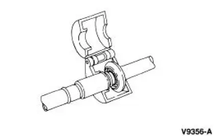
2. Remove the fuel tube clip.
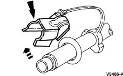
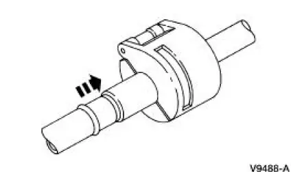
3. Install the Spring Lock Coupler Tool.
4. Close and push the Spring Lock Coupler Tool into the open side of the cage.
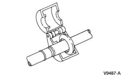
5. Separate the fitting.
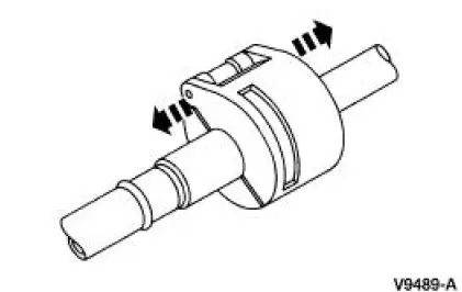
6. Remove the Spring Lock Coupler Tool.
Connect
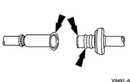
1. NOTE: Inspect and clean both the coupling ends. Lubricate the O-ring seals with clean engine oil.
Connect the fitting.
- Pull on the fitting to make sure it is fully engaged.
- Install the safety clip.
 Fuel Tank Draining
Special Tool(s)
Fuel Storage Tanker
164-R3202 or equivalent
Fuel Tank Drain Hose
310-F013
WARNING: Do not smoke or carry lighted tobacco or an open flame of any
type whe ...
 Fuel Line Fittings - Push Connect
Special Tool(s)
Disconnect Tool, Spring Lock
Coupling
310-S039 (T90T-9550-S)
Material
Item
Specification
SAE 5W-20 Super Premium
Blend Motor Oil
XO-5W20-QSP or equiv ...
Other materials:
Fuel Charging And Controls
The fuel injection supply manifold (9F792):
delivers fuel to the fuel injector.
receives fuel from the fuel supply line.
The throttle body (9E926):
controls air supply to the upper intake manifold (9424) by positioning
the throttle plate.
connects the ...
Module - Daytime Running Lamps (DRL)
Removal
1. CAUTION: Electronic modules are sensitive to static electrical
charges. If exposed
to these charges, damage can result.
Disconnect the battery ground cable.
2. Remove the daytime running lamps (DRL) module and bracket assembly
(15A270).
...
Transmission Connector Layouts
Transmission Vehicle Harness Connector
Transmission Internal Harness Connector
Digital Transmission Range (TR) Sensor Connector
Output Shaft Speed (OSS) Sensor Harness Connector
Digital Transmission Range (TR) Senso ...
