Ford Mustang (1999-2004) Service Manual: Fuel System (Description and Operation)
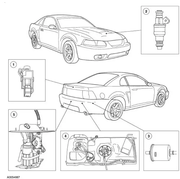
Component Location
WARNING: Do not smoke or carry lighted tobacco or open flame of any type when working on or near any fuel-related components. Highly flammable mixtures are always present and may be ignited, resulting in possible personal injury.
The vehicle:
- uses a returnless fuel system.
- is equipped with a multiport fuel injection (MFI) system.
- uses separately controlled fuel injectors (9F593) for each cylinder. The fuel injectors are mounted to the intake manifold.
- fuel injectors are supplied with pressurized fuel from the fuel pump (9350) through the fuel injection supply manifold (9D280).
- fuel injection supply manifold is controlled by the electronic fuel delivery module which is enabled by the powertrain control module (PCM) (12A650).
Fuel System
Refer to the Powertrain Control/Emissions Diagnosis (PC/ED) manual.
 Fuel System - General Information
General Specifications
...
 Pressure Relief
Special Tool(s)
Fuel Pressure Gauge
310-012 (T80L-9974-B)
WARNING: Do not smoke or carry lighted tobacco or open flame of any
type when
working on or near any fuel-related components. ...
Other materials:
Child restraint and safety belt maintenance
Inspect the vehicle safety belts and child safety seat systems periodically
to
make sure they work properly and are not damaged. Inspect the vehicle
and child seat safety belts to make sure there are no nicks, tears or cuts.
Replace if necessary. All vehicle ...
Entertainment
Your system offers many media options. You can access these options
using the touchscreen or voice commands.
AM/FM Radio
Press the RADIO hard button.
To change between AM, FM1 and FM2, touch the AM or FM
tab. You can also access satellite radio by pressing t ...
Exterior Trim and Ornamentation
Torque Specifications
Exterior Trim and Ornamentation
The exterior trim and ornamentation consists of the following
components:
body side scoop
hood scoop (if equipped)
front spoiler (Mach 1)
radiator grille
rear spoiler (if equipped)
...
