Ford Mustang (1999-2004) Service Manual: Halfshaft
Special Tool(s)
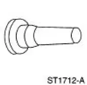 |
Differential Plug 205-294 (T89P-4850-B) |
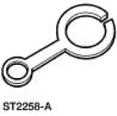 |
Differential Seal Protector 205-461 |
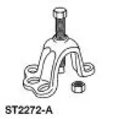 |
Front Hub Remover 205-D070 (D93P-1175-B) or Equivalent |
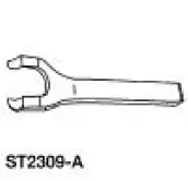 |
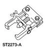
Halfshaft Removal Tool 205-475 |
 |
Steering Arm Remover 211-003 (T64P-3590-F) |
 Rear Drive Halfshafts (Description and Operation)
The rear wheel drive halfshaft system consists of and operates as
follows:
Halfshafts (4K138) transmit engine torque from the rear axle housing to
the rear wheels.
Halfshafts rotate at approxi ...
 Removal
NOTE: This procedure applies to both the LH and RH halfshafts.
1. CAUTION: The vehicle must be on level ground and at curb height.
Mark the rear shock absorber relative to the protective sleeve.
...
Other materials:
General Maintenance Information
NOTE: This is a generic maintenance schedule for all Ford, Lincoln and
Mercury vehicles. There may
be items listed that do not apply to all vehicles.
The Normal Schedule applies to operation of the vehicle under typical, everyday
driving conditions.
The ma ...
Safety Belt Maintenance
WARNING: All safety belt assemblies include retractors, buckles, front
seat belt buckle
support assemblies (slide bar, if so equipped), shoulder belt height adjuster
(if equipped), child
safety seat tether bracket assemblies (if equipped) and attaching hardw ...
Air Conditioning (A/C) System Flushing
Special Tool(s)
A/C Flush and Purge Machine
219-00022 (part of 219-00023)
or equivalent
A/C Flush and Purge Fitting Kit
219-00024 (part of 219-00023)
or equivalent
WARNING: Use extreme care and observe all safety and service
...
