Ford Mustang (1999-2004) Service Manual: Halfshaft Joint
Special Tool(s)
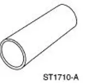 |
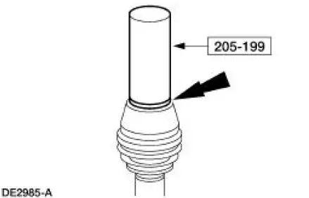
Driver 205-199 (T83T-3132-A1) |
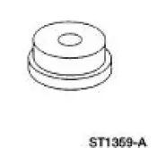 |
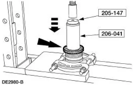
Hub Bearing Cup Replacer 205-147 (T80T-4000-P) |
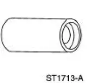 |
Sensing Ring Replacer 206-041 (T89P-20202-A) |
Disassembly
1. CAUTION: Do not disassemble the halfshaft assembly. Install a new assembly if worn or damaged.
Remove the halfshaft from the vehicle. For additional information, refer to Halfshaft in this section.
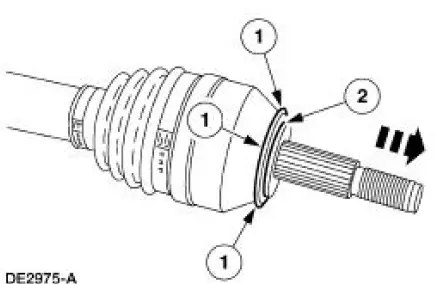
2. If necessary, remove the dust seal assembly (2217).
1. Tap uniformly around the dust seal assembly.
2. Slide the dust seal assembly from the shaft.
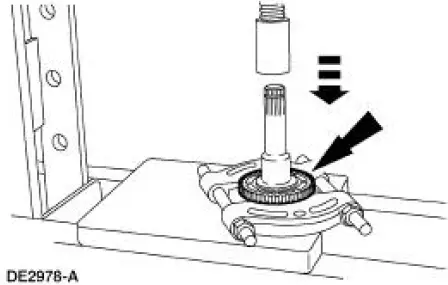
3. Using a suitable bearing plate and a press, remove the rear brake anti-lock sensor indicator, if necessary.
Assembly
1. Using the special tool and a hammer, install the new dust seal assembly, if removed.
2. CAUTION: Place only the inboard CV joint outer race land on the bearing plate. Do not press against any other portion of the outer race or damage will occur.
If removed, using the special tools, the bearing plate and a suitable press, seat the rear brake anti-lock sensor indicator against the inboard CV joint housing.
3. Install the halfshaft in the vehicle. For additional information, refer to Halfshaft in this section.
 Installation
1. NOTE: This procedure applies to both the LH and RH halfshafts.
Install a new driveshaft bearing retainer circlip.
2. Remove the special tool.
3. CAUTION: Differential seal damage will occur if i ...
 Brake System
...
Other materials:
Pinpoint Test K: LFC 35/DTC B1935 - Passenger Air Bag Circuit Resistance
Low
Normal Operation
The restraints control module (RCM) monitors the resistance of the
passenger air bag ignitor by
measuring the resistance between pins 6 and 7. If the RCM detects low
resistance between these
pins, it will store a diagnostic trouble code ...
Air Cleaner Element - 3.8L
Removal and Installation
1. Remove the air cleaner outlet tube. For additional information, refer
to Air Cleaner Outlet Pipe-
3.8L in this section
2. Disconnect the connector.
3. Remove the mass air flow (MAF) sensor.
1. Release the clips.
2. Re ...
Removal
CAUTION: Suspension fasteners are critical parts because they affect
performance of vital
components and systems and their failure can result in major service expense. A
new part with
the same part number must be installed if installation becomes necessary. ...
