Ford Mustang (1999-2004) Service Manual: Fuel Vapor Control Tube Assembly Valve
Removal and Installation
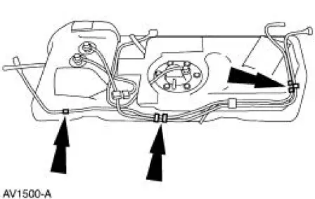
1. Remove the fuel tank. For additional information, refer to Section.
2. Remove the retainers.
3. NOTE: The fuel vapor vent valve, fuel vapor control valve and the in-line fuel tank pressure sensor are repaired as a fuel vapor control valve tube assembly.
NOTE: It may be necessary to lubricate the fuel vapor control valve tube assembly grommets with ESE-M00B144-B Merpol or equivalent to assist in the removal procedure.
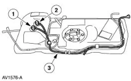
Remove the fuel vapor control valve tube assembly.
1. Loosen the fuel vapor vent valve.
2. Loosen the fuel vapor control valve.
3. Remove the fuel vapor control valve tube assembly.
4. NOTE: Lubricate all O-ring seals with MERPOL O-Ring Seal Lubricant or equivalent meeting Ford specification ESE-M99B144-B.
NOTE: New grommets are necessary when the fuel vapor control valve tube assembly is removed.
To install, reverse the removal procedure.
- Leak test the system. For additional information, refer to Evaporative Emission System Leak Test in this section.
- Carry out the evaporative emission repair verification drive cycle. For additional information, refer to Evaporative Emission Repair Verification Drive Cycle in this section.
Fuel Tank Pressure Sensor
Removal and Installation
1. NOTE: The in-line fuel tank pressure sensor is repaired along with the fuel vapor vent valve and the fuel vapor control valve as a fuel vapor control valve tube assembly.
For removal and installation of the fuel vapor control valve, refer to Fuel Vapor Control Tube Assembly Valve in this section.
 Evaporative Emission Canister Purge Valve
Removal and Installation
1. WARNING: The evaporative emission system contains fuel vapor
and condensed
fuel vapor. Although not in large quantities, it still presents the
danger of explosion ...
 Evaporative Emission Test Port
Removal and Installation
1. Disconnect the pin-type retainer.
2. Raise and support the vehicle. For additional information, refer to
Section.
3. Remove the RH front wheel. For additional informa ...
Other materials:
Engine and Radiator Flushing
Special Tool(s)
Coolant System
Drain/Flush/Fill
164-R3673 or equivalent
Flush Kit
164-R3658 or equivalent
Drain Kit
164-R3662 or equivalent
Material
Item
Specification
Motorcraft Premium Cooling
...
Fuel Vapor Control Tube Assembly Valve
Removal and Installation
1. Remove the fuel tank. For additional information, refer to
Section.
2. Remove the retainers.
3. NOTE: The fuel vapor vent valve, fuel vapor control valve and the
in-line fuel tank pressure
sensor are repaired as a fuel va ...
Pinpoint Tests - OSC Equipped Vehicles
Special Tool(s)
Breakout Box, EEC-V Control
System
418-049 (T94L-50-EEC-V) or
equivalent
MLP-TR Cable
418-F107 (007-00111) or
equivalent
Worldwide Diagnostic System
(WDS)
418-F224
New Generation STAR (NGS)
T ...
