Ford Mustang (1999-2004) Service Manual: Installation
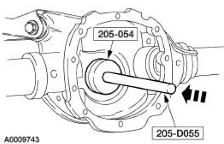
Using special tool 205-054
NOTE: This is the preferred method for installing the pinion bearing cups. If necessary, proceed to Using special tools 205-153, 205-054, and 205-D055 in this procedure for an alternate method.
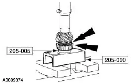
1. Position the special tools and the inner and outer pinion bearing cups in their respective bores.
1. After placing the inner and outer bearing cups in their bores, place the special tool on the inner bearing cup.
2. Place the special tool on the outer bearing cup.
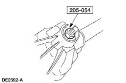
3. Install the special tool.
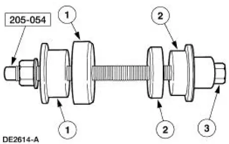
2. Tighten the special tool to seat the pinion bearing cups in their bores.
3. CAUTION: Always install new differential pinion bearings when installing new pinion bearing cups.
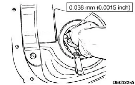
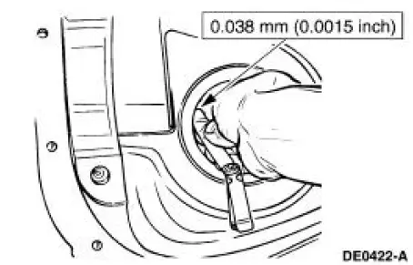
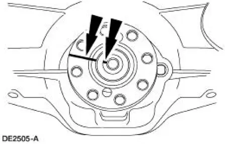
NOTE: If the feeler gauge can fit between a cup and the bottom of its bore at any point around the cup, remove and reseat the cup.
Check that the cups have seated correctly in their bores.
Using special tools 205-153, 205-054, and 205-D055
NOTE: This is an alternate method for installing the pinion bearing cups. Carry out this procedure if pinion bearing cup installation was not done in the previous steps.
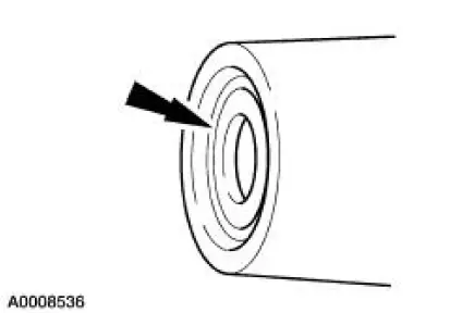
4. Using the special tools, drive the outer differential drive pinion bearing cup (4616) into the differential housing.
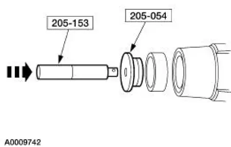
5. Using the special tools, drive the inner rear axle pinion bearing cup (4628) into the differential housing.
6. CAUTION: Always install new differential pinion bearings when installing new pinion bearing cups.
NOTE: If the feeler gauge can fit between a cup and the bottom of its bore at any point around the cup, remove and reseat the cup.
Check that the cups have seated correctly in their bores.
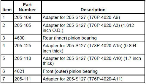
Setting pinion depth
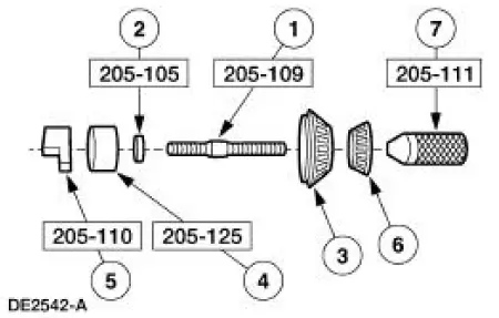
7. NOTE: Apply only a light oil film on the differential pinion bearings before assembling the tools.
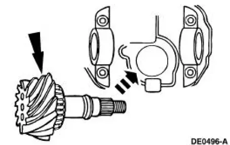
Assemble and position the following in the differential housing.
1. Position the Adapter for 205-S127.
2. Position the Adapter for 205-S127.
3. Position the inner pinion bearing.
4. Position the Adapter for 205-S127.
5. Position the Adapter for 205-S127.
6. Position the outer pinion bearing.
7. Thread on the Adapter for 205-S127.
8. NOTE: This step duplicates final differential pinion bearing preload.
Using a Nm (inch/pound) torque wrench, tighten the special tool to specification.
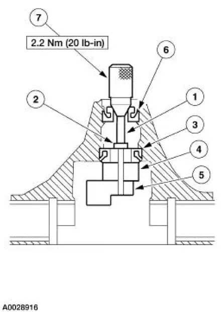
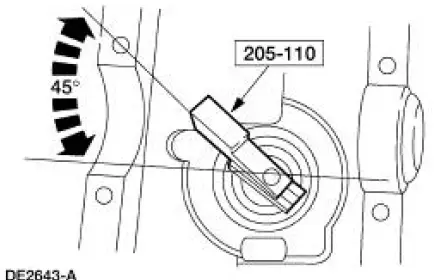
9. NOTE: Offset the special tool to obtain an accurate reading.
Rotate the special tool several half-turns to make sure the differential pinion bearings seat correctly and position the special tool as shown.
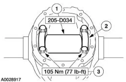
10. Install the special tool.
1. Position the special tool.
2. Install the bearing caps.
3. Install the four bolts.
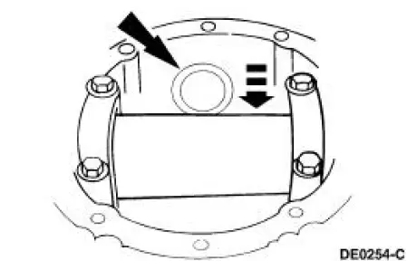
11. NOTE: Use only flat, clean drive pinion bearing adjustment shims (4663).
NOTE: Selection of too thick a shim results in a deep tooth contact at final assembly. Do not attempt to force the shim between the special tools. A slight drag indicates correct shim selection.
Use a drive pinion bearing adjustment shim as a gauge for shim selection.
- After determining the correct shim thickness, remove the special tools.
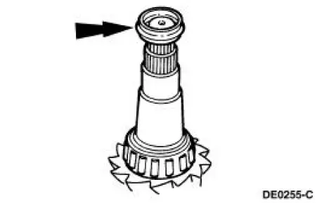
12. Position the correct thickness drive pinion bearing adjustment shim and the differential pinion bearing on the drive pinion gear. Using a suitable press and the special tools, press the differential pinion bearing until it seats firmly against the drive pinion gear.
13. Place a new collapsible spacer on the pinion shaft against the pinion stem shoulder.
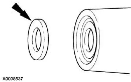
14. Install the outer differential pinion bearing.
15. Install the rear axle drive pinion shaft oil slinger.
16. Install the drive pinion assembly (drive pinion, shims, bearing, and the collapsible spacer) into the differential housing bore.
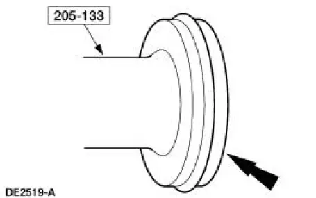
17. NOTE: Coat the rear axle drive pinion seal lips with Premium Long-Life Grease XG-1-C or equivalent meeting Ford specification ESA-M1C75-B.
Place the rear axle drive pinion seal on the special tool.
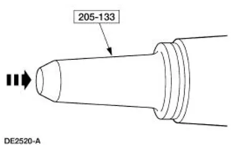
18. CAUTION: If the rear axle drive pinion seal becomes misaligned during installation, remove it and install a new one.
Position the rear axle drive pinion seal in the seal bore, and use the special tool to drive the seal into place.
19. Lubricate the pinion flange splines.
- Use SAE 80W-90 Premium Rear Axle Lubricant XY-80W90-QL or equivalent meeting Ford specification WSP-M2C197-A.
20. NOTE: Disregard the index marks if installing a new pinion flange.
Position the pinion flange.
21. Using the special tools, install the pinion flange.
22. CAUTION: Do not under any circumstance loosen the nut to reduce preload. If it is necessary to reduce preload, install a new collapsible spacer and nut.
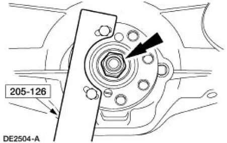
CAUTION: Remove the special tool while taking readings with the Nm (inch-pound) torque wrench.
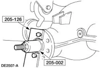
Tighten the nut to set the preload.
- Rotate the drive pinion occasionally to make sure the differential pinion bearings seat correctly. Take frequent differential pinion bearing torque preload readings by rotating the drive pinion with a Nm (inch-pound) torque wrench.
- For new differential pinion bearings, tighten the nut to specification. Refer to torque specifications for new differential pinion bearings in the Specifications portion of this section.
- For used differential pinion bearings, if the preload recorded prior to disassembly is lower than the specification for used bearings, then tighten the nut to specification. Refer to torque specifications for used differential pinion bearings in the Specifications portion of this section.
- For used differential pinion bearings, if the preload recorded prior to disassembly is higher than the specification for used bearings, then tighten the nut to the original reading as recorded.
 Removal
1. Remove the differential assembly from the differential housing. For
additional information, refer
to Differential Case in this section.
2. CAUTION: Record the torque necessary to maintain rotatio ...
Other materials:
Symptom Chart
NOTE: New speed control diagnostic software is available in Version 12
or higher for the diagnostic
tool. When using this software, it is necessary to use Next Generation Speed
Control Adapter 007-
00586 with the diagnostic tool.
NOTE: Refer to the Wiring Di ...
Main Control Valve Body
Special Tool(s)
Gauge, Transmission Solenoid
Connectors
307-426
Removal
1. Drain transmission fluid and remove the transmission fluid pan and
filter. For additional
information, refer to Fluid Pan, Gasket and Filter .
2. CAUTION: Do not ...
In California (U.S. Only)
California Civil Code Section 1793.2(d) requires that, if a manufacturer
or its representative is unable to repair a motor vehicle to conform to the
vehicle’s applicable express warranty after a reasonable number of
attempts, the manufacturer shall be requir ...
