Ford Mustang (1999-2004) Service Manual: Removal
1. Remove the differential assembly from the differential housing. For additional information, refer to Differential Case in this section.
2. CAUTION: Record the torque necessary to maintain rotation of the drive pinion gear through several revolutions prior to removing the pinion flange (4851).
Remove the pinion flange. For additional information, refer to Drive Pinion Flange and Drive Pinion Seal in this section.
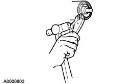
3. Force the rear axle drive pinion seal metal flange up. Install gripping pliers and strike with a hammer to remove the seal.
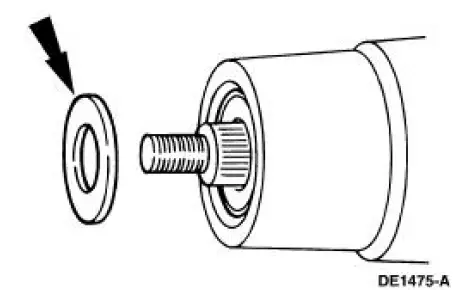
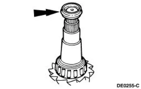
4. Remove the rear axle drive pinion shaft oil slinger (4670).
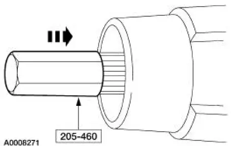
5. Using the special tool and a soft-faced hammer, drive the pinion assembly out of the outer differential pinion bearing (4621) and remove the drive pinion through the rear of the differential housing (4010).
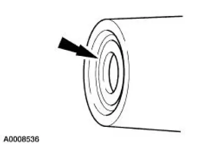
6. Remove the outer differential pinion bearing.
7. Remove and discard the collapsible spacer (4662).
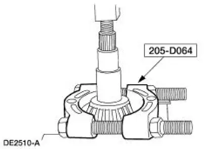
8. Using the special tool and a suitable press, remove the inner differential pinion bearing (4630).
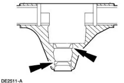
9. NOTE: Do not remove the pinion bearing cups from the differential housing unless the cups are damaged.
To remove the bearing cups, tap alternately (with a brass drift of suitable length) on opposite sides of the cup to prevent the cup from cocking in the casting.
 Drive Pinion
Special Tool(s)
Adapter for 205-S127
205-105 (T76P-4020-A3)
Adapter for 205-S127
205-109 (T76P-4020-A9)
Adapter for 205-S127
205-110 (T76P-4020-A10)
Adapter fo ...
 Installation
Using special tool 205-054
NOTE: This is the preferred method for installing the pinion bearing
cups. If necessary, proceed to
Using special tools 205-153, 205-054, and 205-D055 in this procedure for ...
Other materials:
Engine Mount LH
Special Tool(s)
Lifting Bracket, Engine
303-D088 (D93P-6001-A2)
Support Bar, Engine
303-290-A
Removal
1. Install the special tool.
2. Install the special tools.
3. Raise and support the vehicle. For additional information, ref ...
Child seat positioning
WARNING: Airbags can kill or injure a child in a child seat.
Never place a rear-facing child seat in front of an active airbag.
If you must use a forward-facing child seat in the front seat, move the
vehicle seat upon which the child seat is installed all th ...
Switch - Deactivator
Removal
1. Disconnect the battery ground cable.
2. Remove the deactivator switch.
1. Disconnect the deactivator switch electrical connector.
2. Detach the lower deactivator switch hook.
3. Detach the upper deactivator pivot.
Installation
1. N ...
