Ford Mustang (1999-2004) Service Manual: Negative and Positive Camber
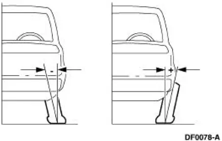
Camber is the vertical tilt of the wheel (1007) when viewed from the front. Camber can be positive or negative and has a direct effect on tire wear.
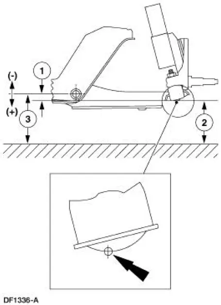
Caster
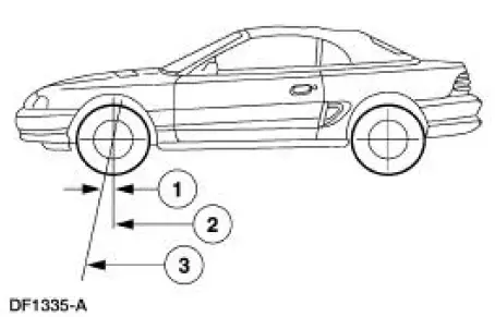
| Item | Part Number | Description |
| 1 | - | Positive caster |
| 2 | - | True vertical |
| 3 | - | Steering axis |
Caster is the deviation from vertical of an imaginary line drawn through the ball joints when viewed from the side. Caster specifications in this section will give the vehicle the best directional stability characteristics when loaded and driven. Caster setting is not related to tire wear.
Toe
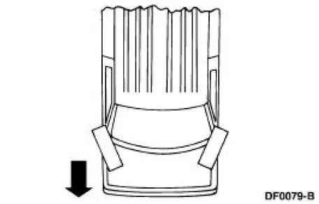
Positive Toe (Toe In)
Negative Toe (Toe Out)
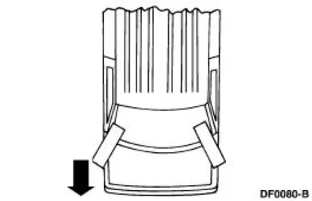
The vehicle toe setting affects tire wear and directional stability.
Ride Height
Front Ride Height Measurement
| Item | Description |
| 1 | Ride height = B - A |
| 2 | Measurement A |
| 3 | Measurement B |
 Wheel Alignment Angles
Camber and toe are adjustable on the front suspension systems. Front camber
is adjusted by moving
the top of the strut and spring assembly. Rear camber is adjusted by means of
eccentric cams on the
...
 Rear Ride Height Measurement - GT and Base
Item
Description
1
Body reinforcement
2
Ride height (shortest distance)
3
Rear axle
Wheel Track
Item
Part Number
Description
1
-
Front track
...
Other materials:
Fuel Tank Filler Pipe
Removal
1. Remove the fuel tank. For additional information, refer to Fuel Tank in
this section.
2. Remove the bolts from the filler pipe housing.
3. Remove the bolts from the filler pipe rubber boot-to-floor pan.
4. Remove the hose attached to the upper p ...
Disassembly
1. Inspect the clutch cylinder thrust surfaces, piston bore and clutch plate
serrations for scores or
burrs. Minor scores or burrs may be removed with crocus cloth. Install a new
clutch cylinder if it
is badly scored or damaged.
2. Check the fluid passage i ...
Removal
1. Disconnect the electrical connectors from the EGR vacuum regulator
solenoid, the
supercharger bypass vacuum solenoid, and the differential pressure
feedback EGR system.
2. Disconnect the vacuum hoses from the differential pressure feedback EGR
sy ...
