Ford Mustang (1999-2004) Service Manual: Removal
WARNING: Do not smoke or carry lighted tobacco or open flame of any type when working on or near any fuel related components. Highly flammable mixtures are always present and may be ignited. Failure to follow these instructions may result in personal injury.
WARNING: Fuel in the fuel system remains under high pressure even when the engine is not running. Before working on or disconnecting any of the fuel lines or fuel system components, the fuel pressure must be relieved. Failure to follow these instructions may result in personal injury.
1. Disconnect the battery ground cable (14301). For additional information, refer to Section.
2. Disconnect the air cleaner outlet tube. For additional information, refer to Section.
3. Relieve the fuel pressure. For additional information, refer to Section.
4. Disconnect the fuel line. For additional information, refer to Section..
5. Remove the throttle body (9E926). For additional information, refer to Throttle Body in this section.
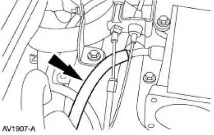
6. Remove the idle air control (IAC) hose and position it out of the way.
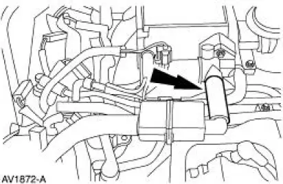
7. Remove the positive crankshaft ventilation (PCV) hose.
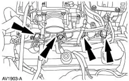
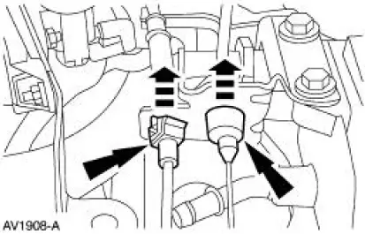
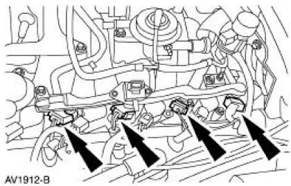
8. Disconnect the four RH fuel injector electrical connectors.
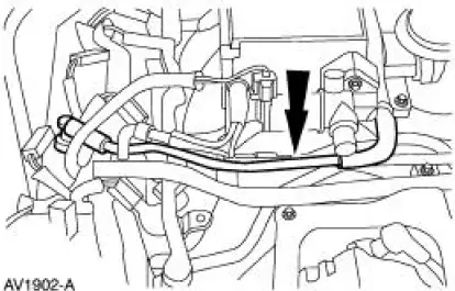
9. Disconnect the IAC electrical connector and the main chassis vacuum hose.
10. Remove the hose.
11. Squeeze the two locking tabs, and remove the accelerator cable and the speed control cable (if equipped) and position aside.
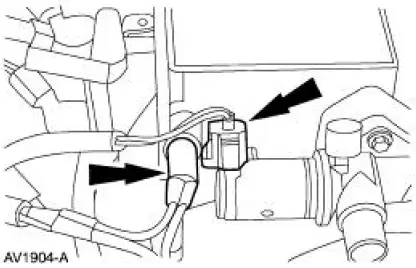
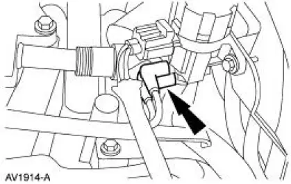
12. Disconnect the fuel pressure sensor electrical connector and the vacuum hose.
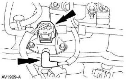
13. Disconnect the ground wire.
14. Disconnect the LH fuel injector electrical connectors.
15. Remove the exhaust vacuum regulator (EVR) solenoid vacuum lines.
16. Remove the bolts from the EGR pressure transducer bracket and position aside.
17. Remove the EGR to exhaust manifold tube. For additional information, refer to Section.
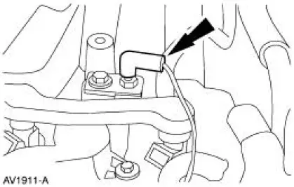
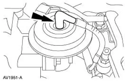
18. Disconnect the exhaust valve recirculation (EGR) vacuum line.
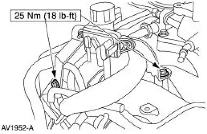
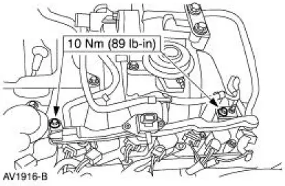
19. NOTE: The LH side is shown, the RH is similar.
Remove the four bolts and remove the supply manifold with the fuel injectors attached.

 Installation
1. NOTE: The LH side is shown, and the RH is similar.
Install the supply manifold and tighten the four bolts.
2. Connect the EGR vacuum line.
3. Install the EGR to exhaust manifold tube. For ad ...
Other materials:
Transmission Cooling - Integral
This vehicle with an automatic transmission is equipped with an integral
transmission fluid cooler. The
cooler is contained inside of the radiator outlet tank and cannot be serviced
separately. The cooler
transfers heat from the transmission fluid to the eng ...
Supply Manifold
Removal and Installation
WARNING: Do not smoke or carry lighted tobacco or open flame of any
type when
working on or near any fuel related components. Highly flammable mixtures are
always present
and may ignite. Failure to follow these instructions may resul ...
Engine Coolant Temperature (ECT) Sensor - Cobra
Material
Item
Specification
Pipe Sealant with Teflon
D8AZ-19554-A
WSK-M2G350-A2
Removal and Installation
1. Partially drain the engine cooling system. For additional
information, refer to Section.
2. Disconnect the engine coolant te ...
