Ford Mustang (1999-2004) Service Manual: Installation
1. CAUTION: The actuator adjustment tool included with the replacement actuator kit must be used when installing the supercharger bypass vacuum actuator. Failure to correctly adjust the actuator will result in incorrect operation of the supercharger assembly.
Install the actuator adjustment tool onto the actuator, making sure the tool is correctly attached to the actuator rod. rotate the actuator into position until the rod engages the lever.
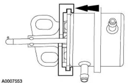
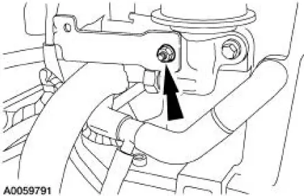
2. Install the actuator.
- Align the actuator rod with the slot in the linkage.
3. Install the actuator bolts.
4. Remove the actuator adjustment tool.
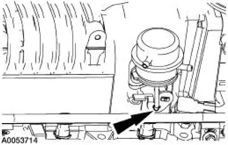
5. Install the vacuum accessory bracket, and the mounting bolts.
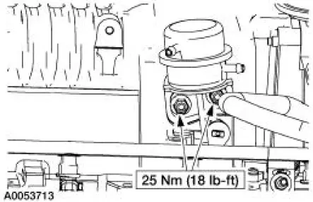
6. Install the vacuum accessory bracket mounting nut.
7. Connect the vacuum hoses to the EGR vacuum regulator solenoid.
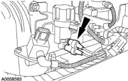
8. Connect the vacuum hoses to the supercharger bypass vacuum solenoid, and the actuator.
9. Connect the vacuum hoses to the differential pressure feedback EGR system.

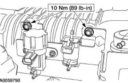
10. Connect the electrical connectors to the EGR vacuum regulator solenoid, the supercharger bypass vacuum solenoid, and the differential pressure feedback EGR system.
 Removal
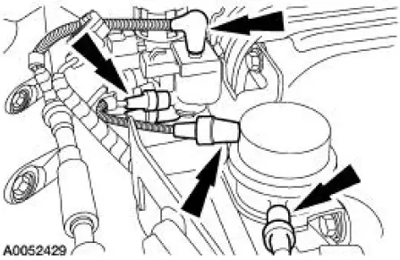
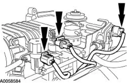
1. Disconnect the electrical connectors from the EGR vacuum regulator
solenoid, the
supercharger bypass vacuum solenoid, and the differential pressure
feedback EGR system.
2. Disconnect the ...

Other materials:
Emission control system
WARNING: Do not park, idle, or drive your vehicle in dry grass
or other dry ground cover. The emission system heats up the
engine compartment and exhaust system, which can start a fire.
WARNING: Exhaust leaks may result in entry of harmful and
potentially leth ...
Information
Under the Information menu, you can access features such as Where Am
I? and Sirius Travel Link, view your calendar, see system information and
get basic system help.
Press the I (Information) hard button to access these features.
Where Am I?
Press the I butt ...
Installation
1. Using the special tools, install the new intake valve stem seals.
2. Using the special tools, install the new exhaust valve stem seals.
3. Install the Valve Spring Compressor Spacer between the valve spring coils
to protect the intake
valve stem seal f ...
