Ford Mustang (1999-2004) Service Manual: Intake Manifold Runner Control (IMRC) Actuator - 3.8L
Removal and Installation
1. Disconnect the battery ground cable. For additional information, refer to Section.
2. Drain the cooling system. For additional information, refer to Section.
3. Remove the upper intake manifold. For additional information, refer to Section.
4. Remove the fuel injector supply manifold. For additional information, refer to Section.
5. Remove the coolant bypass tube. For additional information, refer to Section.
6. Remove the bolt and heater water inlet tube at the back of the lower intake.
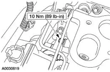
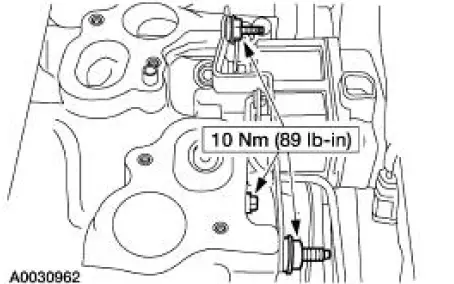
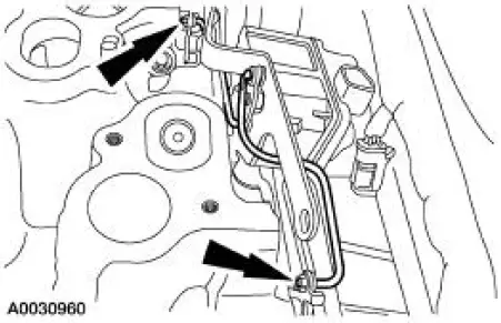
7. Remove the two stud bolts and one bolt. Position the actuator aside.
8. Disconnect the linkage and remove the actuator.
9. NOTE: New plastic IMRC retainers must be installed any time an IMRC rod is removed.
NOTE: Before installing the IMRC actuator, be sure to rotate the motor driver plate until the levers make contact with the set screws, then rotate the motor until the motor bracket bolt holes line up with the tapped holes in the lower intake manifold.
NOTE: Discard O-ring and install a new O-ring on the heater inlet tube. Lubricate the O-ring with engine coolant prior to installation.
To install, reverse the removal procedure.
 Camshaft Position (CMP) Sensor - 4.6L
Removal and Installation
1. Disconnect the battery ground cable. For additional information,
refer to Section.
2. Remove the bolts and position aside the power steering pump
reservoir.
3. ...
 Crankshaft Position (CKP) Sensor - 3.8L
Removal
1. Disconnect the battery ground cable. For additional information,
refer to Section.
2. Remove the crankshaft position (CKP) sensor.
Disconnect the connector.
Remove the bolt ...
Other materials:
Exterior Trim and Ornamentation
Torque Specifications
Exterior Trim and Ornamentation
The exterior trim and ornamentation consists of the following
components:
body side scoop
hood scoop (if equipped)
front spoiler (Mach 1)
radiator grille
rear spoiler (if equipped)
...
Water Bypass Hose - 3.8L
Removal and Installation
1. Drain the engine coolant. For additional information, refer to Cooling
System Draining, Filling
and Bleeding in this section.
2. Remove the bypass hose.
3. To install, reverse the removal procedure.
4. Fill and bleed the co ...
Warning lamps and indicators
These indicators can alert you to a vehicle condition that may become
serious enough to cause expensive repairs. Many lights will illuminate
when you start your vehicle to make sure they work. If any light remains
on after starting the vehicle, refer to the re ...
