Ford Mustang (1999-2004) Service Manual: Bushing - Stabilizer Bar
Removal
CAUTION: Suspension fasteners are critical parts because they affect performance of vital components and systems and their failure can result in major service expense. A new part with the same part number or an equivalent part must be installed, if installation is necessary. Do not use a part of lesser quality or substitute design. Torque values must be used as specified during reassembly to ensure correct retention of these parts.
1. Raise the vehicle on a hoist.
2. Remove the wheel and tire assemblies.
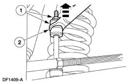
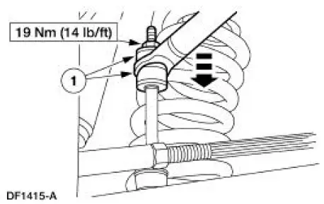
3. Disconnect the front stabilizer bar links (5K483) from the front stabilizer bar (5482).
1. Remove the nuts and bushings. Discard the nuts.
2. Rotate the stabilizer bar to disconnect the links.
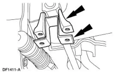
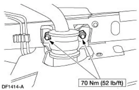
4. Remove and discard the nuts.
5. Remove the stabilizer bar bracket (5486) and the stabilizer bar mounting bracket adapter (5B482).
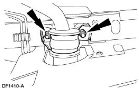
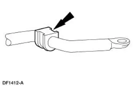
6. Cut the stabilizer bar insulators (5493) from the stabilizer bar.
Installation
1. NOTE: To aid installation, coat the necessary parts of the front stabilizer bar and the inside diameter of the stabilizer bar bushing with Rubber Suspension Insulator Lube E25Y-19553-A or equivalent meeting Ford specification ESF-M99B112-A.
To install, reverse the removal procedure.
 Link - Stabilizer Bar
Removal
CAUTION: Suspension fasteners are critical parts because they affect
performance of vital
components and systems and their failure can result in major service expense. A
new part with
the sa ...
 Spindle
Special Tool(s)
Tie-Rod End Remover
211-001 (TOOL-3290-D) or
Equivalent
Removal
CAUTION: Suspension fasteners are critical parts because they affect
performance of vital
components and ...
Other materials:
Negative and Positive Camber
Camber is the vertical tilt of the wheel (1007) when viewed from the front.
Camber can be positive or
negative and has a direct effect on tire wear.
Caster
Item
Part Number
Description
1
-
Positive caster
2
-
True vertical
...
Warning Indicator Bulb
Removal and Installation
1. Remove the instrument cluster. Refer to Instrument Cluster in this
section.
2. Remove the necessary instrument cluster bulbs by rotating one quarter
turn counterclockwise.
3. To install, reverse the removal procedure.
...
Cylinder Head
Special Tool(s)
Compressor, Valve Spring
303-163 (T81P-6513-A)
Material
Item
Specification
SAE 5W-20 Premium Synthetic
Blend Motor Oil
XO-5W20-QSP or equivalent
WSS-M2C153-
H
Disassembly and Assembly
CAUTION: If the com ...
