Ford Mustang (1999-2004) Service Manual: Lumbar Motor
Removal and Installation
All vehicles
1. Remove the front seat. For additional information, refer to Seat-Front Power in this section.
2. Disconnect the power seat track electrical connector.
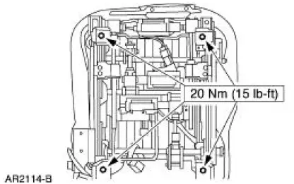
3. Remove the four seat track bolts.
Vehicles with standard power lumbar
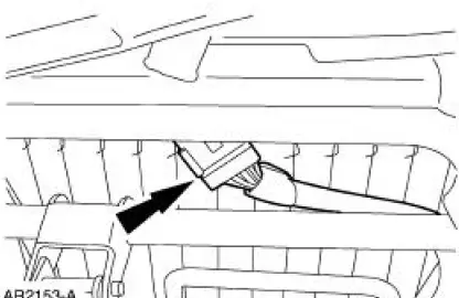
4. Release the J-clip.
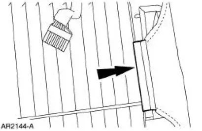
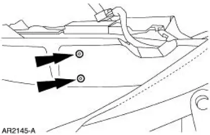
5. Remove the front seat backrest pad adjusting pump screws.
6. Remove the front seat backrest pad adjusting pump (65530).
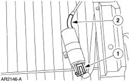
1. Disconnect the electrical connector.
2. Disconnect the power lumbar support air hose.
Vehicles with power bolster and lumbar
7. Remove the driver seat backrest latch. For additional information, refer to Latch-Front Seat Backrest in this section.
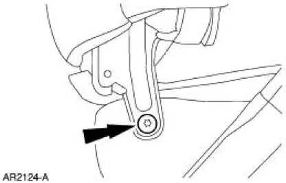
8. Remove the pivot bolt and seat backrest.
- Disconnect the power lumbar support air hoses.
9. Release the J-clips.
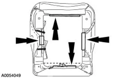
10. NOTE: When removing the cushion from the frame, it is not necessary to remove the trim cover from the cushion foam pad.
Remove the cushion foam pad from the frame.
11. NOTE: The lumbar and bolster pump and solenoid module is serviced as part of the cushion frame assembly.
Install a new seat cushion frame assembly.
All vehicles
12. To install, reverse the removal procedure.
 Seat Track
Removal and Installation
1. Remove the front seat. For additional information, refer to Seat-Front
Power in this section.
2. Remove the outboard seat trim shield.
3. Disconnect the electrical c ...
 Latch - Front Seat Backrest
Removal
NOTE: The power seat backrest adjuster assembly must be installed as a
new unit. Repair of the
power seat backrest adjuster assembly components is not acceptable and
should not be attemp ...
Other materials:
Exterior Lighting
Torque Specifications
Exterior Lighting
The exterior lighting system consists of the following components:
headlamps (13008)
parking lamps
rear lamps (13404)
high mounted stoplamp
license lamps
front turn lamps
reversing lamps
fog ...
Body System - General Information
General Specifications
Body
Body and Sheet Metal
The body:
Is a unibody open cowl structure.
Is constructed of a lightweight, all-steel material with
removable bolted hood (16612), front
fenders (16005), doors, and luggage compartment lid ...
Instrument Panel and Console
Torque Specifications
Instrument Panel
The instrument panel consists of the following components:
instrument cluster
instrument panel finish panels
audio unit
A/C controls
glove compartment door
passenger air bag module
glove compart ...
