
Ford Mustang (1999-2004) Service Manual: Manual Transmission and Clutch (Description and Operation)
The primary function of the clutch is to couple and uncouple engine power to the transmission upon driver command. For additional information, refer to Section.
Clutch Disc and Clutch Pressure Plate - 3.8L
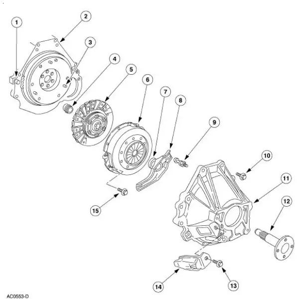
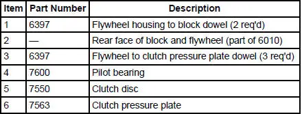
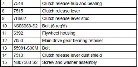
Clutch Disc and Clutch Pressure Plate - 4.6L (2V)
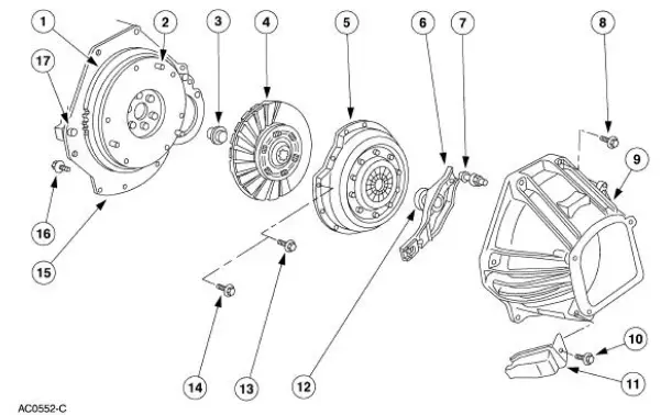
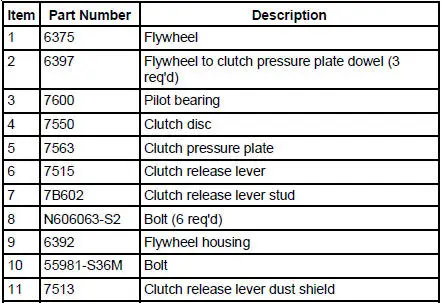
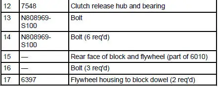
Clutch Disc and Clutch Pressure Plate - 4.6L (4V)
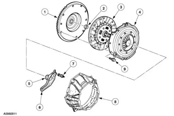
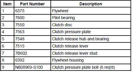
- The clutch is a single plate, dry friction clutch disc. The clutch disc has a splined hub with integral torsional springs. The clutch disc hub attaches to the input shaft.
- Engine output is coupled to the transmission input shaft by friction existing between the clutch disc facings and the flywheel/clutch pressure plate assembly. The extent of this friction is directly related to the composition of the facing material and the magnitude of the clamping forces exerted by the clutch pressure plate and the flywheel on the facings. These factors limit the amount of torque that can be transmitted without slippage.
- The clamping force is obtained from a diaphragm spring contained within the clutch pressure plate assembly. This force is developed during the attachment of the clutch pressure plate assembly to the flywheel.
- The clutch system is disengaged when the clutch pedal is pressed and is accomplished when the release fingers are fully displaced toward the flywheel. This displacement removes the spring load from the clutch pressure plate and eliminates the coupling friction between the engine and the transmission.
- When the clutch pedal is depressed a cable connected to the clutch release lever, hub and bearing actuates the clutch pressure plate diaphragm spring, releasing pressure on the clutch disc. This eliminates the engagement between the transmission and the engine.
 Manual Transaxle/Transmission and Clutch - General
Information
Manual Transaxle/Transmission and Clutch - General
Information
General Specifications
...
 Manual Transmission and Clutch (Diagnosis and Testing)
Inspection and Verification
It is important to get an accurate description of the concern before
any diagnosis can be carried out.
Ask questions as to whether it occurs when hot or cold, durin ...
Other materials:
Pinpoint Test J: LFC 34/DTC B1934 - Driver Air Bag Circuit Resistance Low
Normal Operation
The restraints control module (RCM) monitors the resistance of the driver
air bag ignitor by measuring
the resistance between pins 3 and 4. If the RCM detects low resistance
between these pins, it will
store a diagnostic trouble code (D ...
Assembly
1. Carry out the following before reassembling:
Inspect the gears for broken or cracked teeth. Check for unusual wear
patterns.
Inspect the thrust washers for face wear, cracks, scoring and for signs
of heat damage.
Inspect the bearings, bearing cups a ...
Component Tests
Engine Oil Leaks
NOTE: When diagnosing engine oil leaks, the source and location of
the leak must be positively
identified prior to repair.
Prior to carrying out this procedure, clean all sealing surface areas with a
suitable solvent to remove all
tra ...
