Inspection and Verification
It is important to get an accurate description of the concern before
any diagnosis can be carried out.
Ask questions as to whether it occurs when hot or cold, during shifting,
driving at a particular speed or
in a particular gear. If possible, have the customer demonstrate the
concern.
- With the vehicle at a complete stop, shift through all the gears
and evaluate the noise at
different engine rpm. Check for any noises in NEUTRAL at different
engine rpm.
Symptom Chart
| Condition |
Possible Sources |
Action |
|
|
- Clutch pedal
sticking.
- Pressure plate
diaphragm
spring damaged
or weakened.
- Clutch pressure
plate damaged.
- Clutch disc
facing damaged
or worn
excessively.
- Clutch disc
facing surface
hardened or oilcoated.
- Clutch release
hub and bearing
binding.
- Flywheel glazed
or damaged.
- loose pressure
plate to flywheel
bolts
|
|
- Clutch chatter or shudder
|
- Loose or worn
engine mount.
- Loose pressure
plate to flywheel
bolts
- Oil on clutch
disc facing.
- Clutch pressure
plate damaged or excessive
runout.
- Clutch disc
facing surface
hardened or
damaged.
- Flywheel
surface glazed
or damaged.
- Transmission
input shaft
eccentric or not
perpendicular.
|
|
|
|
- Clutch drag.
- Cable release
linkage outside
the flywheel
housing worn,
cracked, bent.
- Excessive
runout or
damaged clutch
disc.
- Clutch disc
splines rusted or
worn.
- Loose pressure
plate to flywheel
bolts.
|
|
|
|
- Clutch disc
damaged or
worn.
- Excessive
flywheel runout.
- Loose pressure
plate to flywheel
bolts.
- Improperly
assembled
release lever to
pivot stud.
|
|
- Clutch related vibrations
|
- Engine
component
grounding
against frame.
- Loose flywheel
bolts.
- Excessive
flywheel runout.
- Imbalanced
clutch pressure
plate.
- Accessory drive
belt loose or
damaged.
|
|
|
|
- Manual
transmission
concern.
- Loose pressure
plate to flywheel
bolts.
|
|
|
|
- Pilot bearing
worn or
damaged.
- Excessive
crankshaft end
play.
|
|
- Transmission difficult to
shift
|
- Lubricant.
- Internal shift
mechanism.
- Sliding gears,
synchronizers
- Housings, shaft.
- Loose pressure
plate to flywheel
bolts.
|
|
- NOTE: While verifying
the condition, determine
whether the noise is gear
rollover noise, release
bearing rub or some
other transmissionrelated
noise. Gear
rollover noise, inherent in
manual transmissions, is
caused by the constant
mesh gears turning at the
engine idle speed while
the clutch is engaged and
the transmission is in
NEUTRAL. Release
bearing rub is sometimes
mistaken for mainshaft
bearing noise. Gear
rollover noise will
disappear when the
clutch is disengaged or
when the transmission is
engaged in gear. Release bearing rub will
disappear when the
clutch is engaged. In the
event that a bearing is
damaged, the noise is
more pronounced while
engaged in gear under
load or coast than in
NEUTRAL.
Noisy in forward gears
|
- Lubricant.
- Components
grounding out
on the
transmission.
- Components
housing bolts
- Bearings or
gears.
|
|
- Gears clash when
shifting from one forward
gear to another
|
- Pilot bearing.
- Gear teeth
and/or
synchronizer.
- Engine idle
speed too high.
|
- CHECK for a binding
condition between the
input shaft and the
engine crankshaft pilot
bearing. INSTALL new
components as
necessary
- REPAIR or INSTALL
new components as
necessary
- REFER to the
Powertrain
Control/Emissions
Diagnosis (PC/ED)
manual
|
- Transmission jumps out
of gear
|
- Transmission
range selector
lever boot
- Transmission-toengine
mounting
bolts
- Crankshaft pilot
bearing.
- Internal
damage.
- Gear teeth.
|
|
- Transmission will not shift
into one gear-all others
OK
|
- Manual shift
linkage.
- Backup switch
ball
- Internal
components.
|
|
- Transmission is locked in
one gear and cannot be
shifted out of that gear
|
- Internal
components
- Fork on rail.
|
- INSPECT the problem
gears, shift rails, forks
and the synchronizer for
wear or damage.
REPAIR as necessary.
- CHECK the shift rail
interlock system
|
|
|
- Lubricant
- Other
component
leaking
- False report.
- Internal
components.
- Fill and drain
plugs
|
- CHECK the level and
type.
- IDENTIFY leaking fluid
as engine, power
steering, or transmission
fluid. REPAIR as
necessary
- REMOVE all traces of
lube on the exposed
transmission surfaces.
CHECK the vent for free
breathing. OPERATE
the transmission and
INSPECT for new
leakage. REPAIR as
necessary
- INSPECT for leaks at
the input shaft bearing
retainer seal and the
shift rail expansion plug. INSPECT for leaks
at the top cover gasket.
INSPECT the case for
sand holes or cracks.
REPAIR or INSTALL a
new case as necessary.
- CHECK fill and drain
plugs and bore threads.
REPAIR as necessary.
TIGHTEN plugs to
specified torque value.
|
|
|
- Vibration breakup
of retainer
and brinelling of
races.
- Bearing(s).
- Shafts or bore.
- Overloading of
vehicle.
- Incorrect
preload.
- Input shaft oil
dam.
- Oil baffle in the
input bearing
shim pack.
|
- REMOVE,
DISASSEMBLE and
CLEAN the
transmission. Inspect for
damaged parts and
install new components
as necessary. (Note:
RESET the bearing
preload if any new
tapered bearings are
installed).
- DETERMINE the cause
of vibration and
CORRECT. Otherwise
PROCEED as above.
- Install new components
as necessary and verify
the oil dam installation is
correct.
CHECK for correct
installation of the snap
ring on the mainshaft
next to the oil dam.
- INSTALL a new oil
baffle, making sure it is
not damaged during
assembly.
|
Pinpoint Tests
PINPOINT TEST A: CLUTCH SLIPPAGE
| Test Step |
Result / Action to Take |
| A1 INSPECT THE CLUTCH LINKAGE |
Yes GO to A2 .
No
INSPECT the clutch pedal |
- Key in OFF position.
- Block the wheels and apply the parking brake.
- Depress and slowly release the clutch pedal.
- Does the clutch pedal release without
binding?
|
| A2 CARRY OUT A STALL TEST |
Yes The clutch is not slipping. VERIFY the
customer concern.
No
INSPECT the clutch components for
damage. |
- Key in START position.
- Block the wheels and apply the parking brake.
- Place the transmission in fourth gear.
- Increase the engine speed to 2000 rpm and
slowly release the clutch pedal.
- Does the engine stall within five seconds?
|
PINPOINT TEST B: CLUTCH CHATTER OR SHUDDER
| Test Step |
Result / Action to Take |
| B1 CHECK ENGINE OR TRANSMISSION MOUNTS |
Yes TIGHTEN or INSTALL new engine
mounts or transmission mounts. TEST
the system for normal operation.
No
GO to B2 . |
- Inspect all the engine and transmission mounts
for looseness or damage.
- Are any of the engine or transmission mounts loose or damaged?
|
| B2 INSPECT PRESSURE PLATE BOLTS |
Yes TIGHTEN or INSTALL new bolts.
REFER to Section. TEST the
system for normal operation.
No
GO to B3 . |
- Inspect the pressure plate-to-flywheel bolts.
- Are any of the pressure plate-to-flywheel bolts
loose?
|
| B3 INSPECT PRESSURE PLATE |
Yes INSTALL a new clutch pressure plate.
REFER to Section. TEST the
system for normal operation.
No
GO to B4 . |
- Remove the clutch pressure plate. Refer to
Section
- Inspect the clutch pressure plate. Refer to
Pressure Plate Check .
- Are any signs of damage present on the clutch
pressure plate?
|
| B4 CHECK CLUTCH DISC |
Yes GO to B5 .
No
INSTALL a new clutch disc. REFER to
Section. TEST the system for
normal operation. |
- Carry out the clutch disc inspection procedure.
Refer to Disc Check .
- Is the clutch disc OK?
|
| B5 INSPECT THE FLYWHEEL |
Yes GO to B6 .
No
REPAIR or INSTALL a new flywheel
as necessary. REFER to Section. TEST the system for normal
operation |
- Inspect the flywheel for damage and runout. Refer
to Flywheel Runout Check .
- Is the flywheel OK?
|
| B6 INSPECT THE INPUT SHAFT |
Yes INSTALL a new input shaft.
No
VERIFY the customer concerns. GO
to Symptom Chart if necessary. |
- INSPECT the input shaft for signs of wear or
damage.
- Are any signs of wear or damage present on
the input shaft?
|
PINPOINT TEST C: CLUTCH DRAG
| Test Step |
Result / Action to Take |
| C1 CHECK HIGH SHIFTING EFFORTS |
Yes Clutch system OK.
No
CHECK the clutch pressure plate and clutch
disc. INSTALL a new clutch pressure plate
or clutch disc if necessary. TEST the system for
normal operation |
- Key in START position.
- Set parking brake.
- With the shift control selector in REVERSE, clutch disengaged
and engine idling, move
the shift lever to a position halfway between
REVERSE and NEUTRAL.
- Slowly engage clutch. The transmission will
behave as if it is in NEUTRAL.
- Gear clash can now be heard if an attempt
is made to shift into REVERSE with the
clutch engaged. Reserve can now be
measured.
- While maintaining light pressure on the shift
selector, slowly press the clutch pedal to the
floor. The gear clash will stop and the shift
selector will slide into the REVERSE
position.
- Is there a minimum 19.05 mm (0.750 inch)
clutch pedal reserve?
|
PINPOINT TEST D: CLUTCH PEDAL PULSATION
| Test Step |
Result / Action to Take |
| D1 CHECK THE CLUTCH PEDAL
PULSATION |
Yes GO to D2 .
No
VERIFY customer concern. GO to Symptom
Chart if necessary. |
- Key in START position.
- With the transmission in NEUTRAL,
slowly press the clutch pedal.
- Does the clutch pedal pulsate while
being pressed?
|
| D2 INSPECT PRESSURE PLATE BOLTS |
Yes TIGHTEN or INSTALL new bolts. TEST the
system for normal
operation.
No
GO to D3 . |
- Inspect the pressure plate-to-flywheel
bolts.
- Are any of the pressure plate-toflywheel
bolts loose?
|
| D3 INSPECT THE CLUTCH PRESSURE
PLATE |
Yes INSTALL a new clutch pressure plate.
TEST the system for normal
operation.
No
GO to D4 . |
- Remove the clutch pressure plate.
- INSPECT the clutch pressure plate for
damage. Refer to Pressure Plate
Check .
- Are there any signs of damage
present on the clutch pressure plate?
|
| D4 INSPECT THE CLUTCH DISC |
Yes GO to D5 .
No
INSTALL a new clutch disc. TEST the system for normal operation. |
- Carry out the clutch disc inspection
procedure. Refer to Disc Check .
- Is the clutch disc OK?
|
| D5 INSPECT THE FLYWHEEL |
Yes GO to D6 .
No
TIGHTEN, RESURFACE or INSTALL a new
flywheel as necessary. TEST the system for normal operation. |
- Inspect the flywheel for damage and
runout. Refer to Flywheel Runout
Check .
- Is flywheel OK?
|
| D6 INSPECT RELEASE LEVER
INTERFACE TO PIVOT STUD |
Yes INSTALL a new pivot stud and release
lever.TEST the system
for normal operation.
No
VERIFY customer concern. GO to Symptom
Chart if necessary. |
- Inspect the release lever and the pivot
stud for damage or misalignment.
- Are there any signs of damage
present or misalignment between the
release lever and pivot stud?
|
PINPOINT TEST E: CLUTCH RELATED VIBRATIONS
| Test Step |
Result / Action to Take |
| E1 CHECK FOR ENGINE COMPONENT
GROUNDING |
Yes REPAIR the components as necessary.
TEST the
system for normal operation.
No
GO to E2 . |
- Raise the vehicle on a hoist.
- Check the engine and transmission
mounts for grounding.
- Check for exhaust manifolds or other
engine component grounding on the
body or frame.
- Is there evidence of grounding on
the body or frame?
|
| E2 CHECK FOR ACCESSORY DRIVE
VIBRATIONS |
Yes REFER to Section to diagnose the
accessory drive belt components.
No
STOP the engine and INSTALL the drive belt. GO
to E3 . |
- Key in START position.
- Remove the accessory drive belt.
- Does the vibration stop when the
accessory drive belt is removed
from the engine?
|
| E3 CHECK FOR RELEASE BEARING
NOISE |
Yes INSTALL a new clutch release hub and
bearing.
REFER to Section.
No
GO to E4 . |
- Key in START position.
- Depress and hold the clutch pedal.
- Is a whirring, grating, or grinding
noise present only when pedal is
pushed?
|
| E4 INSPECT THE FLYWHEEL |
Yes VERIFY customer concern. GO to Symptom
Chart if necessary.
No
TIGHTEN, RESURFACE or INSTALL a new
flywheel. REFER to Section. TEST the
system for normal operation. |
- Key in OFF position.
- Remove the transmission.
- Carry out a flywheel check. Refer to
Flywheel Runout Check .
- Is the flywheel OK?
|
PINPOINT TEST F: HARD SHIFTING
| Test Step |
Result / Action to Take |
| F1 CHECK THE CLUTCH RELEASE CABLE |
Yes REPAIR or INSTALL a new
clutch release cable as
necessary. TEST the
system for normal
operation.
No
GO to F2 . |
- NOTE: Check the upper shift boot for twisting.
- NOTE: Check the engine idle speed.
- Inspect the clutch release cable for wear or damage. Make
sure the clutch release cable is correctly routed and that all
the fasteners are installed.
- Are there any fasteners missing or is the cable worn,
damaged or incorrectly routed?
|
| F2 CHECK THE CLUTCH PEDAL |
Yes VERIFY customer concern.
TEST the system for
normal operation.
No
GO to F3 . |
- Loosen the clutch pedal shaft nut.
- Lift the clutch pedal to the most upward position.
- While holding the clutch pedal in the most upward position,
tighten the nut.
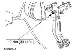
- Was the clutch pedal incorrectly adjusted?
|
| F3 CHECK THE CLUTCH PEDAL QUADRANT |
Yes INSTALL a new quadrant.
TEST the system for
normal operation.
No
GO to F4 . |
- Pull up on the clutch pedal to the upstop. Pulling up on the
pedal ensures that the quadrant is free to rotate through it's
complete range of motion against the spring load of the
quadrant.
- Is the clutch pedal quadrant binding?
|
| F4 MEASURE THE CLUTCH RESERVE |
Yes INSTALL a new pressure
plate and clutch disc.
REINSTALL the
transmission. RECHECK
the clutch reserve. TEST
the system of normal
operation.
No
GO to F5 . |
| NOTE: Do not check the clutch system after the
road test.
Allow the vehicle to cool down before carrying out the clutch
reserve check. NOTE: Remove the floor mat, if equipped, to
allow the clutch pedal to travel to the downstop.
- Install a cable tie to the lower clutch pedal, than attach a
tape measure to the cable tie.
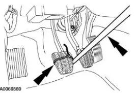
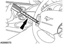
- Pull the tape measure up to the steering wheel. Position it
through the steering wheel opening.
- Depress the clutch fully and start the vehicle.
- Shift the transmission into reverse gear, then move the shift
lever forward to the position in between reverse gear and
neutral. Slowly release the clutch pedal (if the vehicle creeps
rearward, move the shift lever forward a little more). The
transmission will behave as if in neutral, but the reverse gear
synchronizer will be bypassed.
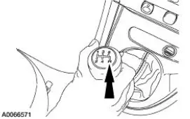
- With the clutch pedal up, gently pull the shift lever toward the
reverse gear position. Gear clash can now be heard.
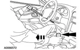
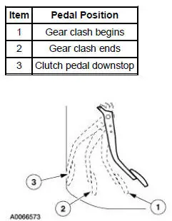
- Is the clutch reserve less than 19 mm (0.75 inch)?
|
| F5 INSPECT THE RELEASE LEVER AND PIVOT STUD |
Yes INSTALL a new release
lever or pivot stud as
necessary. TEST the
system for normal
operation.
No
GO to F6 . |
- Remove the transmission.
- Inspect the release lever and the pivot stud for wear,
damage or misalignment.
- Is the release lever or pivot stud worn, damaged or
misaligned?
|
| F6 INSPECT THE RELEASE BEARING |
Yes INSTALL a new release
bearing. TEST the system
for normal operation.
No
GO to F7 . |
- Inspect the release bearing for wear or damage. Make sure
the release lever is seated in the release bearing pocket.
- Is the release bearing worn or damaged?
|
| F7 INSPECT THE PILOT BEARING |
Yes INSTALL a new pilot
bearing. TEST the system
for normal operation.
No
GO to F8 . |
- Inspect the pilot bearing for wear or damage.
- Is the pilot bearing worn or damaged?
|
| F8 INSPECT THE CLUTCH PRESSURE PLATE TO FLYWHEEL
BOLTS |
Yes INSTALL a new pressure
plate and clutch disc. Note
the condition of the
removed components
(wear, damage or oil
contamination). For oil contamination, REPAIR as
necessary. TEST the
system for normal
operation. If the
transmission is still hard to
shift, GO to F9 .
No
TIGHTEN the bolts to 80
Nm (59 lb-ft). TEST the
system for normal
operation. If the
transmission is still hard to
shift, GO to F9 . |
- Measure the clutch pressure plate to flywheel bolts.
- Is the bolt torque greater than or equal to 65 Nm (48 lbft)?
|
| F9 INSPECT THE TRANSMISSION |
Yes INSTALL new components
or REPAIR as necessary.
TEST the system for
normal operation.
No
ASSEMBLE and INSTALL
the transmission. TEST the
system for normal
operation. |
- Remove the transmission.
- Disassemble the transmission.
- Carry out the following:
- inspect all the shift rails for excessive scuffing or
wear.
- check the interlock pins on the shift rail.
- make sure the interlock bolts are tighten to 31 Nm (23
lb-ft).
- inspect the shift pads for wear or cracking.
- inspect the shift forks for wear or damage.
- check the synchronizer rings (of the affected gear[s])
for wear or damage.
- check the synchronizer hubs (of the affected gear[s])
for wear or damage.
- inspect the clutching teeth of the affected gear.
- Are there any internal components worn or damaged?
|
PINPOINT TEST G: EXCESSIVE NOISE
| Test Step |
Result / Action to Take |
| G1 TRANSMISSION NEUTRAL GEAR ROLLOVER TEST |
Yes INSPECT the clutch component
for damage. REFER to General
Procedures in this section.
No
GO to G2 . |
- Start the engine and let it idle with the transmission in
neutral and the clutch engaged (pedal up). If noise is
excessive, depress the clutch pedal to stop the
transmission input shaft from rotating.
- Does the noise stop when the clutch pedal is
depressed?
|
| G2 CHECK THE PILOT BEARING |
Yes GO to G3 .
No
INSTALL a new pilot bearing. |
- Inspect the pilot bearing for damage. Refer to Bearing .
- Is the pilot bearing OK?
|
| G3 CHECK TORSION SPRINGS |
Yes GO to G3 .
No
INSTALL a new pilot bearing.
No
INSPECT the crankshaft end
play. |
- Inspect the torsion springs for fatigue or breakage.
- Are there any signs of fatigue or breakage?
|
The primary function of the clutch is to couple and uncouple engine
power to the transmission upon
driver command. For additional information, refer to Section.
Clutch Disc and Clutch Pressure ...
Special Tool(s)
Brake/Automobile Brake Drum
System with Vacuum
164-R3622 or equivalent
Dial Indicator/Magnetic Base
100-D002 (D78P-4201-B) or
equivalent
WARNING: Dust ...
Other materials:
Engine - 3.8L
General Specifications
a - 20-200 seconds to leakdown 3.18 mm (0.125 in) with 225 Newtons (50
pounds) load and tappet filled
with leak-down fluid.
Torque Specifications
a - Refer to the procedure in this section
b - Advance one-half turn aft ...
Lumbar Motor
Removal and Installation
All vehicles
1. Remove the front seat. For additional information, refer to Seat-Front
Power in this section.
2. Disconnect the power seat track electrical connector.
3. Remove the four seat track bolts.
Vehicles with standar ...
Crash sensors and airbag indicator
WARNING: Modifying or adding equipment to the front end of
your vehicle (including frame, bumper, front end body structure
and tow hooks) may affect the performance of the airbag system,
increasing the risk of injury. Do not modify the front end of your
vehicl ...
 Manual Transmission and Clutch (Description and Operation)
 Disc Check


