Ford Mustang (1999-2004) Service Manual: Oil Pan
Special Tool(s)
|
|
Compressor, Coil Spring 204-D001 (D78P-5310-A) |
 |
Lifting Bracket, Engine 303-D088 (D93P-6001-A2) |
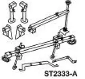 |
3-Bar Engine Support Kit 303-F072 |
Material
| Item | Specification |
| Metal Surface Cleaner F4AZ-19A536-RA or equivalent | WSE-M5B392-A |
| Silicone Gasket and Sealant F7AZ-19554-EA or equivalent | WSE-M4G323- A4 |
| Super Premium SAE 5W-20 Engine Oil XO-5W20-QSP or equivalent | WSS-M2C153-H |
 Oil Level Indicator and Tube
Removal
1. Remove the oil level indicator.
2. Remove the LH exhaust manifold. For additional information, refer to Exhaust
Manifold LH in
this section.
3. Remove the bolt.
4. Remove the oil level ...
 Removal
1. Disconnect the battery ground cable. For additional information, refer to
Section.
2. Remove the transmission.
3. Remove the air intake scoop. For additional information, refer to Section.
4. R ...
Other materials:
Window Glass - Quarter
Removal
1. Remove the quarter trim panel. For additional information, refer
to Section.
2. Remove the roof side trim moulding. For additional information, refer
to Section.
3. Remove the exterior quarter glass weatherstrip.
4. Remove the nuts.
...
Pinpoint Test I: LFC 33/DTC B1933 - Passenger Air Bag Circuit Resistance
High
Normal Operation
The restraints control module (RCM) monitors the resistance of the
passenger air bag ignitor by
measuring the resistance between pins 6 and 7. If the RCM detects high
resistance between these
pins, it will store a diagnostic trouble cod ...
Removal
1. Remove the roller followers. For additional information, refer to Roller
Followers in this section.
2. Remove the LH timing chain for the LH side and both timing chains for the RH
side. For
additional information, refer to Timing Drive Components in this ...
