Ford Mustang (1999-2004) Service Manual: Removal
1. Disconnect the battery ground cable. For additional information, refer to Section.
2. Remove the transmission.
3. Remove the air intake scoop. For additional information, refer to Section.
4. Remove the air cleaner outlet tube. For additional information, refer to Section.
5. Remove the radiator sight shield.
6. Remove the manifold and tube assembly-accumulator to compressor, 4.6L. For additional information, refer to Section.
7. Remove the A/C line. For additional information, refer to Section.
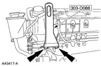
8. Install the special tools.
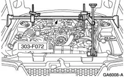
9. Install the special tool.
10. Raise the vehicle on a hoist. For additional information, refer to Section.
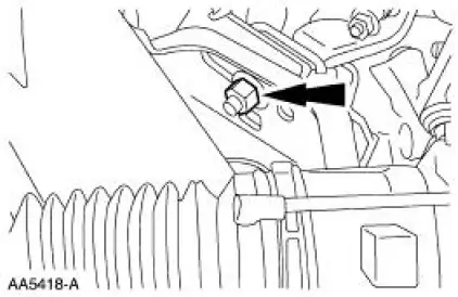
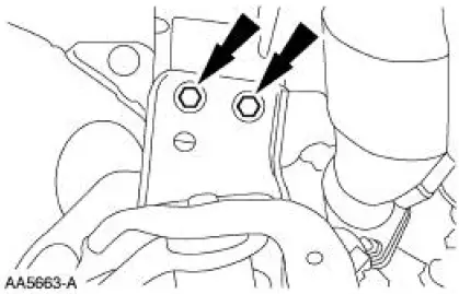
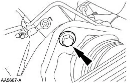
11. Remove the two engine mount nuts.
12. Lower the vehicle.
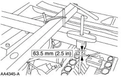
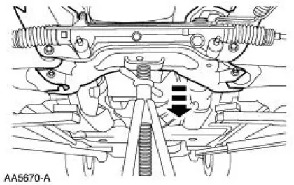
13. Using the special tool, raise the engine.
14. Raise the vehicle on a hoist.
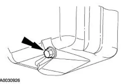
15. Remove the oil pan drain plug and drain the engine oil.
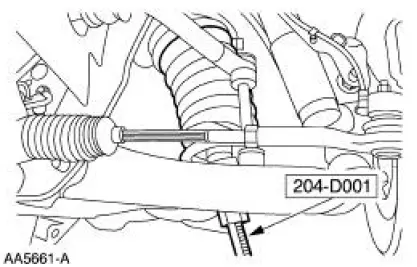
16. Using the special tool, compress the front coil springs.
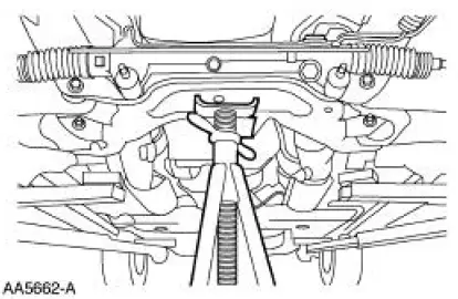
17. Position a safety stand.
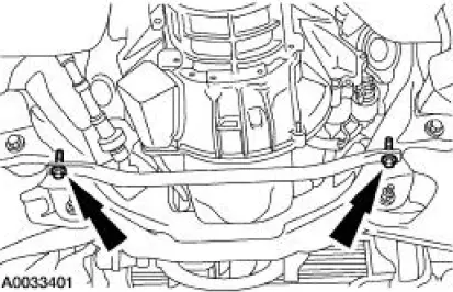
18. Remove the four bolts.
19. NOTE: Do not completely remove the bolts.
Loosen the bolts.
20. Lower the front sub-frame.
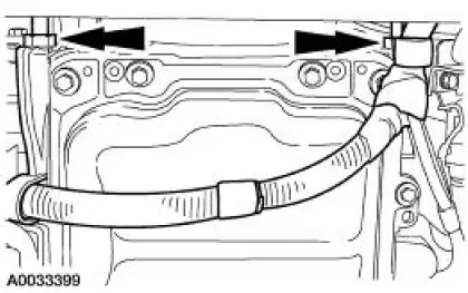
21. Remove the sub-frame brace.
22. Remove the starter wiring harness nuts and position the wiring harness out of the way.
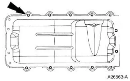
23. NOTE: Be careful when removing the oil pan gasket. It is reusable.
Remove the oil pan and gasket.
- Inspect the oil pan gasket for damage.
 Oil Pan
Special Tool(s)
Compressor, Coil Spring
204-D001 (D78P-5310-A)
Lifting Bracket, Engine
303-D088 (D93P-6001-A2)
3-Bar Engine Support Kit
303-F072
Materia ...
 Installation
1. CAUTION: Do not use metal scrapers, wire brushes, power abrasive
discs or other
abrasive means to clean the sealing surfaces. These tools cause scratches and
gouges
which make leak paths. Use a p ...
Other materials:
Crankshaft Main Bearing Journal - Clearance
Special Tool(s)
Plastigage
303-D031 (D81L-6002-B) or
equivalent
NOTE: Crankshaft main bearing journals must be within specifications
before checking journal
clearance.
1. Remove the crankshaft main bearing caps and crankshaft main bearing.
...
Fuel quality
Note: Use of any fuel other than those recommended may cause
powertrain damage and a loss of vehicle performance; repairs may not be
covered under warranty.
Choosing the Right Fuel
Use only unleaded fuel or unleaded fuel blended with a maximum of
15% ethanol. ...
Muffler - 3.8L
Removal and Installation
1. Raise and support the vehicle. For additional information, refer to
Section.
2. Support the rear axle with a suitable jack.
3. Remove the upper arm-to-differential bolt.
4. Remove the nut and bolt and disconnect the rear shock ...
