Ford Mustang (1999-2004) Service Manual: Installation
1. CAUTION: Do not use metal scrapers, wire brushes, power abrasive discs or other abrasive means to clean the sealing surfaces. These tools cause scratches and gouges which make leak paths. Use a plastic scraping tool to remove all traces of old sealant.
Clean and inspect the mating surfaces.
2. NOTE: If the oil pan is not secured within four minutes, the sealant must be removed and the sealing area cleaned with metal surface cleaner. Allow to dry until there is no sign of wetness, or four minutes, whichever is longer. Failure to follow this procedure may result in future oil leakage.
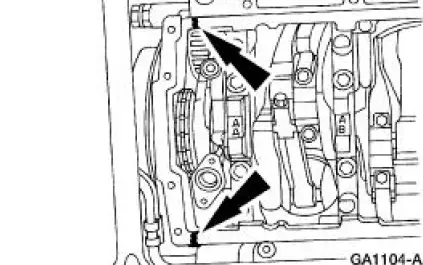
Apply silicone gasket and sealant at the engine front cover-to-cylinder block mating surface.
3. NOTE: If the if the oil pan is not secured within four minutes, the sealant must be removed and the sealing area cleaned with metal surface cleaner. Allow to dry until there is no sign of wetness, or four minutes, whichever is longer. Failure to follow this procedure may result in future oil leakage.
Apply silicone gasket and sealant at the rear oil seal retainer-to-cylinder block sealing surface.
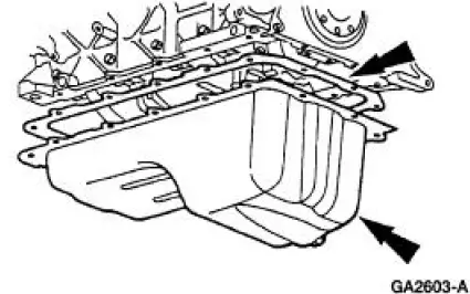
4. Install the oil pan and gasket and loosely install the bolts.
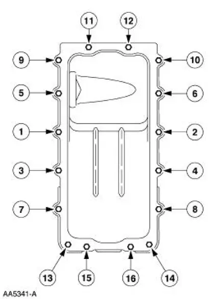
5. Tighten the bolts in the sequence shown in three stages.
- Stage 1: Tighten to 2 Nm (18 lb-in).
- Stage 2: Tighten to 20 Nm (15 lb-ft).
- Stage 3: Tighten an additional 60 degrees.
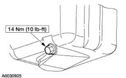
6. Install the oil pan drain plug.
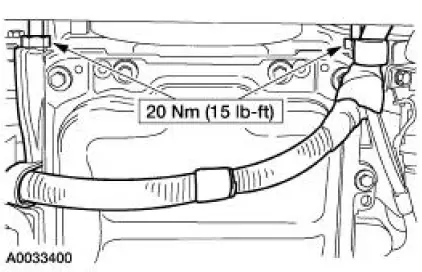
7. Position the starter wiring harness and install the wiring harness nuts.
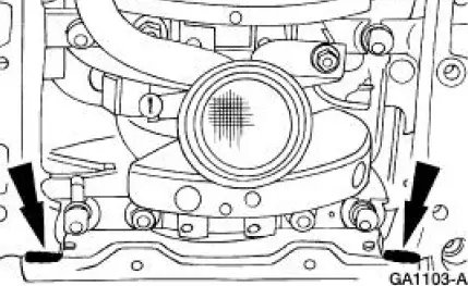
8. Install the sub-frame brace.
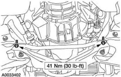
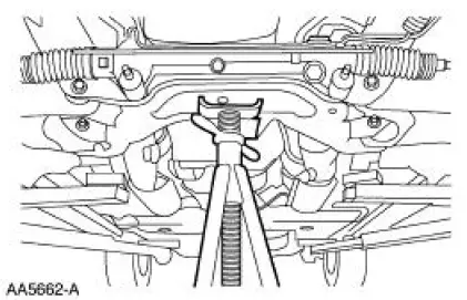
9. Raise the front sub-frame into position.
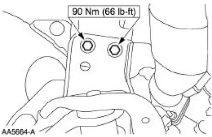
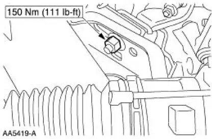
10. Install the two bolts.
11. Install the two bolts.
12. Install the four bolts.
13. Position the safety stand aside.
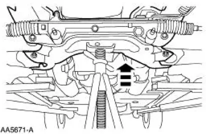
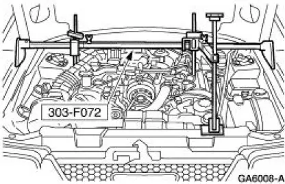
14. Release the tension from the front coil springs and remove the special tool.
15. Raise the vehicle.
16. Using the special tool, lower the engine and remove the special tool.
17. Remove the special tools.
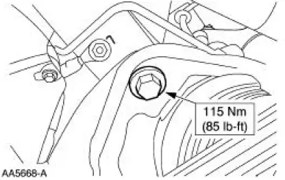
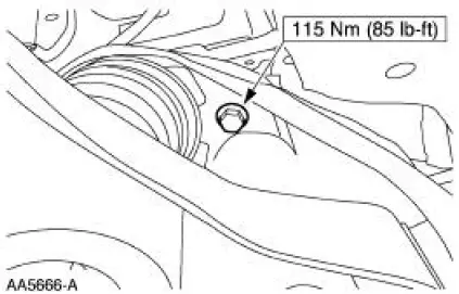
18. Install the two engine mount nuts.
19. Install the transmission.
20. Lower the vehicle.
21. Fill the engine crankcase with clean engine oil.
22. Install the A/C line. For additional information, refer to Section.
23. Install the manifold and tube assembly-accumulator to compressor, 4.6L. For additional information, refer to Section.
24. Install the radiator sight shield.
25. Install the air cleaner outlet tube. For additional information, refer to Section.
26. Install the air intake scoop. For additional information, refer to Section.
27. Install the battery ground cable. For additional information, refer to Section.
28. Start the engine and check for leaks.
Flexplate
1. Remove the transmission. For additional information, refer to Section.
2. Remove the bolts in the sequence shown, and remove the flexplate.
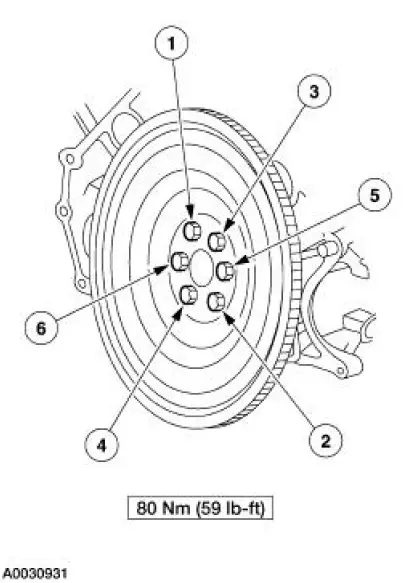
3. To install, reverse the removal procedure.
Flywheel
Removal
1. Remove the clutch components. For additional information, refer to Section.
2. Remove the bolts and the flywheel.
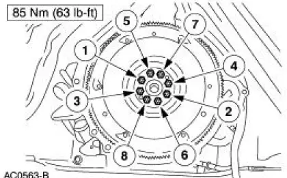
Installation
1. To install, reverse the removal procedure.
 Removal
1. Disconnect the battery ground cable. For additional information, refer to
Section.
2. Remove the transmission.
3. Remove the air intake scoop. For additional information, refer to Section.
4. R ...
 Crankshaft Rear Oil Seal
Special Tool(s)
Installer, Crankshaft Rear Oil
Seal
303-518 (T95P-6701-DH)
Remover, Crankshaft Rear Oil
Seal
303-519 (T95P-6701-EH)
Installer, Crankshaft ...
Other materials:
Diagnostics
Special Tool(s)
Transmission Fluid Pressure
Gauge
307-004 (T57L-77820-A)
Air Test Plate, Transmission
307-246 (T92P-7006-A)
Alignment Gauge, TR Sensor
307-351 (T97L-70010-A)
Breakout Box, EEC-V Control
S ...
Using the boot
Installing the Boot
WARNING: Always secure the retaining clips and boot straps on
the vehicle or the boot may come loose while driving.
Note: Be sure the boot is secure on the vehicle before driving.
Improper
installation can result in loss or damage of the b ...
Warning Indicator Bulb
Removal and Installation
1. Remove the instrument cluster. Refer to Instrument Cluster in this
section.
2. Remove the necessary instrument cluster bulbs by rotating one quarter
turn counterclockwise.
3. To install, reverse the removal procedure.
...
