Ford Mustang (1999-2004) Service Manual: Hydraulic System
Fluid Pump


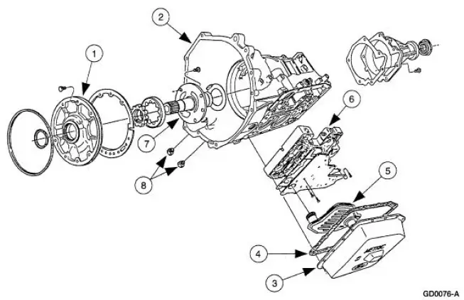
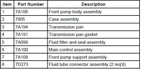
The transmission uses a gerotor-type design front pump support and gear. The pump provides the volume of fluid needed to charge the torque converter, main control assembly, cooling system and lube system. Pump pressure is regulated by the main regulator valve. The pump has an internal boost circuit which is more efficient at lower engine speeds.
Filter
All fluid drawn from the transmission pan by the pump passes through the filter. The filter and its accompanying seal are part of the fluid path from the sump (pan) to the fluid pump.
Main Control
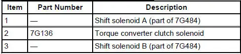
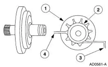
The main control valve body houses three electronic solenoids:
- two shift solenoids
- one torque converter clutch solenoid (TCC solenoid)
Accumulators
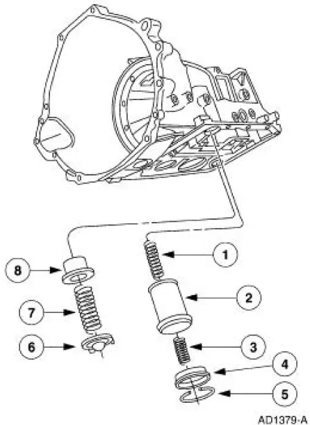
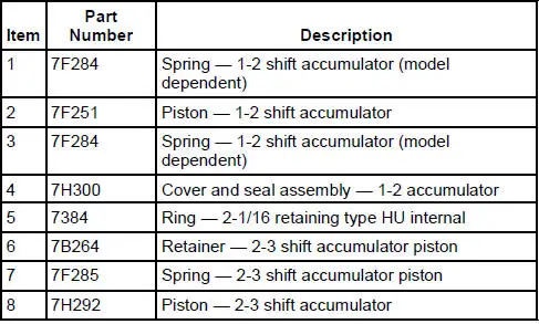
The transmission uses two accumulators:
- 1-2 Accumulator - The 1-2 accumulator is used to soften the 1-2 shift by absorbing some of the pressure directed to the intermediate clutch. Constant line pressure is applied to the middle section of the 1-2 accumulator piston, opposing the intermediate clutch pressure, until the pressure is high enough to overcome line pressure. The top of the piston is exhausted to the sump.
- 2-3 Accumulator - The 2-3 accumulator is used to soften the 2-3
shift by absorbing some of
the direct clutch pressure. Forward clutch pressure is applied to
the top side of the 2-3
accumulator piston, holding the piston down until clutch pressure is
high enough to overcome it.
The middle section of the piston is exhausted to the sump.
 Apply Components
There are eight apply components used to drive or hold the planetary
gearset components.
Band-Overdrive
1. The overdrive band holds the reverse clutch drum stationary in fourth gear
an ...
 Transmission Electronic Control System
The powertrain control module (PCM) and its input/output network
control the following transmission
operations:
Shift timing
Line pressure (shift feel)
Torque converter clutch
Th ...
Other materials:
Fuel Injectors
Removal
WARNING: Do not smoke or carry lighted tobacco or open flame of any
type when
working on or near any fuel related components. Highly flammable mixtures are
always present
and may be ignited. Failure to follow these instructions may result in personal ...
Subwoofer Speaker - Convertible
Removal and Installation
1. Remove the rear quarter trim panel. For additional information,
refer to Section .
2. Remove the subwoofer assembly.
1. Disconnect the electrical connectors.
2. Remove the screws.
3. Remove the subwoofer assemb ...
Cleaning the instrument panel and instrument cluster lens
WARNING: Do not use chemical solvents or strong detergents
when cleaning the steering wheel or instrument panel to avoid
contamination of the airbag system.
Clean the instrument panel and cluster lens with a clean, damp, white,
cotton cloth, then use a clean a ...
