Ford Mustang (1999-2004) Service Manual: Overdrive Servo
Special Tool(s)
 |
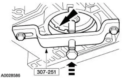
Remover/Installer, Servo Piston 307-251 (T92P-70023-A) |
Removal
1. Remove the main control valve body. For additional information, refer to Main Control Valve Body in this section.
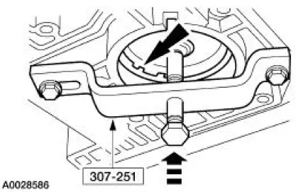
2. NOTE: If the tool is not available, extreme care must be taken. Spring pressure will force overdrive servo piston assembly out of case. Case bore damage may result from trying to pry on overdrive servo internal retaining ring.
Using the special tool, compress the servo spring to remove the overdrive servo retaining ring.
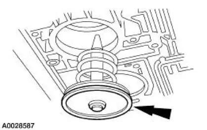
3. Remove the overdrive servo piston and return spring.
Installation
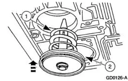
1. Install the overdrive servo piston assembly.
1. Install the overdrive servo piston return spring.
2. Install the overdrive servo piston assembly.
2. Use the special tool to install the overdrive servo piston retaining ring.
3. Install the main control valve body. For additional information, refer to Main Control Valve Body in this section.
 Reverse Servo Assembly
Special Tool(s)
Dial Indicator Gauge with
Holding Fixture
100-002 (TOOL-4201-C)
Remover/Installer, Servo
Piston
307-251 (T92P-70023-A)
Installer, Servo Pisto ...
 1-2 Accumulator
Removal
1. Compress the 1-2 accumulator cover and remove the accumulator piston
retaining ring.
2. NOTE: Note the location of the 1-2 accumulator springs for
reference during assembly.
Remove the ...
Other materials:
Differential Case and Ring Gear
Special Tool(s)
2-Jaw Puller
205-D072 (D97L-4221-A) or
equivalent
Installer, Differential Side
Bearing
205-009 (T57L-4221-A1)
Step Plate
205-D016 (D80L-630-5) or
equivalent
...
Key Programming - Enable/Disable Spare Key
Programming
Special Tool(s)
Worldwide Diagnostic System
(WDS)
418-F224,
New Generation STAR (NGS)
Tester
418-F052, or equivalent
diagnostic tool
NOTE: The spare key programming switch is a diagnostic tool programmable
switch that provides the
ca ...
Inspection and Verification
CAUTION: Do not hold the steering wheel (3600) at the stops for an
extended amount of
time. Damage to the power steering pump (3A674) will result.
NOTE: Make the following preliminary checks before repairing the
steering system:
1. Verify the customer conce ...
