Ford Mustang (1999-2004) Service Manual: Pinpoint Tests
PINPOINT TEST A: THE ENGINE DOES NOT CRANK AND THE RELAY DOES CLICK
| Test Step | Result / Action to Take |
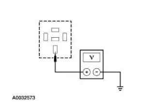
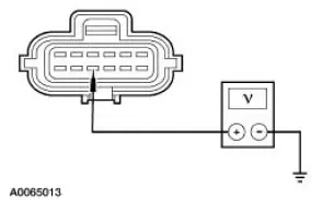
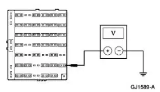
| A1 CHECK THE VOLTAGE TO THE STARTER RELAY | Yes GO to A2 . No REPAIR circuit 1050 (LG/VT) for an open. TEST the system for normal operation. |
|
|
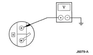
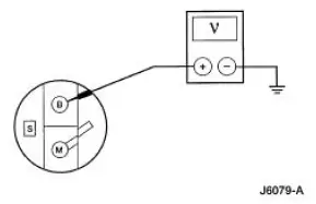
| A2 CHECK THE VOLTAGE TO THE STARTER MOTOR SOLENOID | Yes GO to A3 . No REPAIR circuit 2037 (RD) for an open. TEST the system for normal operation. |
|
|
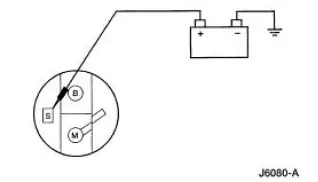
| A3 MANUALLY JUMP THE STARTER MOTOR | Yes GO to A4 . No INSTALL a new starter motor. REFER to Starter Motor-3.8L or Starter Motor-4.6L . TEST the system for normal operation. |
|
|
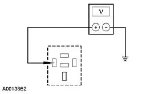
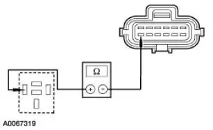
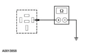
| A4 TEST THE STARTER MOTOR RELAY | Yes REPAIR circuit 33 (WH/PK)/262 (BN/PK) for an open. TEST the system for normal operation. No INSTALL a new starter motor relay. TEST the system for normal operation. |
|
PINPOINT TEST B: THE ENGINE DOES NOT CRANK AND THE RELAY DOES NOT CLICK
| Test Step | Result / Action to Take |
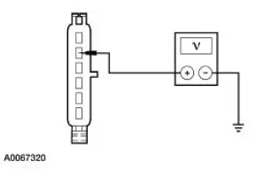
| B1 CHECK CIRCUIT 33 (WH/PK) FOR VOLTAGE | Yes GO to B10 . No For automatic transmissions, GO to B2 . For manual transmissions, GO to B5 . |
|
|
| B2 CHECK CIRCUIT 32 (RD/LB) FOR VOLTAGE AT THE DIGITAL TR SENSOR | Yes GO to B3 . No GO to B7 . |
|
|
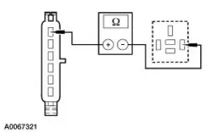
| B3 CHECK CIRCUIT 33 (WH/PK) FOR OPEN | Yes GO to B4 . No REPAIR circuit 33 (WH/PK). TEST the system for normal operation. |
|
|
| B4 CHECK DIGITAL TRANSMISSION RANGE (TR) SENSOR ADJUSTMENT | Yes INSTALL a new digital TR sensor. TEST the system for normal operation. No ADJUST the digital TR as necessary. TEST the system for normal operation. |
|
|
| B5 CHECK CIRCUIT 32 (RD/LB) FOR VOLTAGE AT THE CLUTCH SWITCH OR JUMPER | Yes GO to B6 . No GO to B7 . |
|
|
| B6 CHECK CIRCUIT 33 (WH/PK)/32 (RD/LB) FOR OPEN | Yes INSTALL a new clutch pedal switch. TEST the system for normal operation. No REPAIR circuit 33 (WH/PK)/32 (RD/LB). TEST the system for normal operation. |
|
|
| B7 CHECK FOR VOLTAGE AT FUSE 6 | Yes REPAIR circuit 32 (RD/LB). TEST the system for normal operation. No GO to B8 . |
|
|
| B8 CHECK CIRCUIT 1050 (LG/VT) FOR VOLTAGE | Yes GO to B9 . No REPAIR circuit 1050 (LG/VT). TEST the system for normal operation. |
|
|
| B9 CHECK THE IGNITION SWITCH | Yes REPAIR circuit 33 (WH/PK). TEST the system for normal operation. No INSTALL a new ignition switch. TEST the system for normal operation. |
|
|
| B10 CHECK CIRCUIT 1205 (BK) FOR OPEN | Yes INSTALL a new starter motor relay. TEST the system for normal operation. No REPAIR circuit 1205 (BK). TEST the system for normal operation. |
|

PINPOINT TEST C: THE ENGINE CRANKS SLOWLY
| Test Step | Result / Action to Take |
| NOTE: Before beginning this test, be sure that the battery is tested and fully charged. | |
| C1 CHECK THE VOLTAGE TO THE STARTER | Yes GO to C2 . No REPAIR the circuit between the battery and the starter solenoid. CLEAN and TIGHTEN the connections at the battery terminals. TEST the system for normal operation. |
|
|
| C2 CHECK MOTOR GROUND CIRCUIT | Yes INSTALL a new starter motor. REFER to Starter Motor-3.8L or Starter Motor-4.6L . TEST the system for normal operation. No REPAIR the ground circuit as necessary. TEST the system for normal operation. |
|
|
PINPOINT TEST D: UNUSUAL STARTER NOISE
| Test Step | Result / Action to Take |
| D1 CHECK THE STARTER MOTOR MOUNTING | GO to D2 . No REINSTALL the starter motor correctly. REFER to Starter Motor-3.8L or Starter Motor-4.6L in this section. |
|
|
| D2 INSPECT THE STARTER MOTOR | Yes INSTALL a new starter motor. REFER to Starter Motor-3.8L or Starter Motor-4.6L in this section. TEST the system for normal operation. No CHECK the starter drive. REFER to Component Tests, Starter Drive Test in this section. INSTALL a new starter motor. TEST the system for normal operation. |
|
 Inspection and Verification
WARNING: When servicing starter motor or carrying out other underhood
work in the
vicinity of the starter motor, be aware that the heavy gauge battery input lead
at the starter
solenoid is "electric ...
 Component Tests
Starter Motor -Voltage Drop Test
WARNING: When servicing starter motor or carrying out other underhood
work in the
vicinity of the starter motor, be aware that the heavy gauge battery input lead
at ...
Other materials:
Knob
Removal
1. Remove the shifter top control panel.
2. Disconnect the electrical connectors.
3. Remove the shifter bezel.
4. Remove the bulb from the bezel.
5. Disconnect the TCS connector.
6. CAUTION: Extra force may be needed to lift up on the handle. Do ...
Removal
1. Remove the center instrument panel register.
2. Remove the screws.
3. Disconnect the connectors.
4. Using the special tool, disconnect the temperature control cable from the
control head.
5. Remove the nuts and disconnect the vacuum connector.
...
Throttle Body
Removal and Installation
WARNING: Do not smoke or carry lighted tobacco or open flame of any
type when
working on or near any fuel related components. Highly flammable mixtures are
always present
and may ignite. Failure to follow these instructions may resul ...
