Ford Mustang (1999-2004) Service Manual: Component Tests
Starter Motor -Voltage Drop Test
WARNING: When servicing starter motor or carrying out other underhood work in the vicinity of the starter motor, be aware that the heavy gauge battery input lead at the starter solenoid is "electrically hot" at all times. A protective cap or boot is provided over this terminal that must be installed after servicing. Be sure to disconnect the battery negative cable before servicing the starter. Failure to follow these instructions may result in personal injury.
WARNING: When using a remote starter switch or jumper wire, be sure the ignition switch is in the OFF position and the transmission is in PARK (A/T) or Neutral (M/T) with the parking brake control fully applied.
Always make the Digital Multimeter connections at the component terminal rather than at the wiring end connector. Making a connection at the wiring end connector could result in false readings because the meter will not pick up a high resistance between the wiring connector and the component.
Starter Motor-Motor Feed Circuit
1. Make sure the battery is fully charged. Perform a battery load test. For additional information, refer to Section.
2. Disconnect the inertia fuel shut off (IFS) switch.
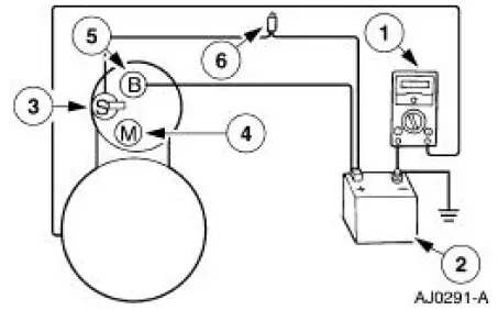
3. Connect a remote starter switch between the starter solenoid S-terminal and the battery positive (+) terminal.
4. Connect the Digital Multimeter positive lead to the battery positive (+) post. Connect negative lead to the starter solenoid M-terminal.
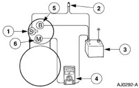
5. Engage the remote starter switch. Read and record the voltage. The voltage reading should be 0.5 volt or less.
6. If the voltage reading is less than 0.5 volts, go to the Starter Motor-Ground Circuit Component Test.
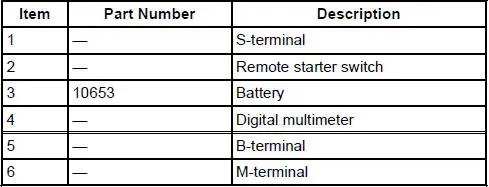
7. If the voltage reading is greater than 0.5 volts, this an indication of excessive resistance in the connections, the positive battery cable or in the starter solenoid. Move the Digital Multimeter negative lead to the starter solenoid B-terminal and repeat the test. If the voltage reading at the B-terminal is less than 0.5 volts, the concern is either in the connections at the starter solenoid or in the solenoid contacts. Go to Step 8. If the voltage reading is greater than 0.5 volts at the Bterminal, the concern is either the positive battery cable or connections. Go to Step 9.
8. Remove the cables from solenoid B-, S- and M-terminals. Clean the cables and connections and reinstall the cables to the correct terminals. Repeat Steps 3 through 6. If the voltage drop reading is still greater than 0.5 volts when checked at the M-terminal and less than 0.5 volts when checked at the B-terminal, the concern is in the solenoid contacts. Install a new starter motor. Refer to Starter Motor-3.8L or Starter Motor-4.6L .
9. Clean the positive (+) battery cable connections. Repeat the test at the starter solenoid B terminal. If the voltage is greater than 0.5 volts, install a new positive battery cable.
Starter Motor-Ground Circuit
A slow cranking condition can be caused by resistance in the ground or return portion of the cranking circuit. Check the voltage drop in the ground circuit as follows:
1. Connect the Digital Multimeter positive lead to the starter motor housing (the connection must be clean and free of rust or grease). Connect the negative lead to the negative (-) battery terminal.
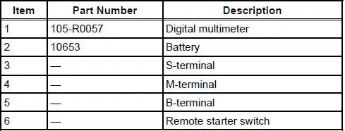
2. Engage the remote starter switch. Read and record the voltage. The voltage reading should be less than 0.3 volts.
3. If the voltage is greater than 0.3 volts, clean the negative cable connections at the battery, body ground connections, and the starter ground connections. Retest.
4. If the voltage is greater than 0.3 volts, install a new cable. If the voltage reading is less than 0.2 volts and the engine still cranks slowly, install a new starter motor. Refer to Starter Motor-3.8L or Starter Motor-4.6L .
 Pinpoint Tests
PINPOINT TEST A: THE ENGINE DOES NOT CRANK AND THE
RELAY DOES CLICK
Test Step
Result / Action to Take
A1 CHECK THE VOLTAGE TO THE STARTER RELAY
YesGO to A2 .
No
REPAIR circuit 1050 ...
 Starter Drive and Flywheel Ring Gear Inspection
1. Remove the starter motor. For additional information, refer to Starter
Motor-3.8L or Starter
Motor-4.6L in this section.
2. Check the wear patterns on the starter drive gear and the flywheel r ...
Other materials:
Accessory Drive Belt Idler Pulley - 4.6L (2V) and (4V)
Removal and Installation
Mach I
1. Remove the air intake scoop. For additional information, refer to Section.
Cobra
2. Remove the supercharger drive belt cover.
3. Rotate the supercharger belt tensioner clockwise and remove the
supercharger belt.
4. Remov ...
Pinpoint Test H: LFC 32/DTC B1932 - Driver Air Bag Circuit Resistance High
Normal Operation
The restraints control module (RCM) monitors the resistance for the
driver air bag ignitor by measuring
the resistance between pins 3 and 4. If the RCM detects high resistance
between these pins, it will
store a diagnostic trouble code ...
Reporting safety defects (U.S. only)
If you believe that your vehicle has
a defect which could cause a crash
or could cause injury or death, you
should immediately inform the
National Highway Traffic Safety
Administration (NHTSA) in addition to notifying Ford Motor Company.
If NHTSA receives si ...
