Ford Mustang (1999-2004) Service Manual: Refrigerant Lines
The condenser to evaporator tube (19835) contains the high pressure liquid refrigerant upstream of the evaporator core orifice.
The A/C manifold and tube (19D734) is attached to the A/C compressor, is sealed with O-ring seals, and has the following features:
- The upstream side contains low pressure refrigerant gas.
- The downstream side contains high pressure refrigerant gas and a fitting used to mount a serviceable high pressure A/C charge port valve.
- The downstream side also contains a fitting used to mount the refrigerant containment switch (3.8L) or dual-function pressure switch (4.6L). A long-travel Schrader-type valve stem core is installed in the fitting so that the switch can be removed without discharging the A/C system.
A/C Evaporator Core
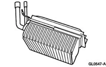
NOTE: The evaporator core is not separately serviceable, it is serviced only with the evaporator core housing assembly.
NOTE: Installation of a new suction accumulator is not required when repairing the air conditioning system except when there is physical evidence of contamination from a failed A/C compressor or damage to the suction accumulator.
The A/C evaporator core is the plate/fin type with a unique refrigerant flow path.
- A mixture of refrigerant and oil enters the bottom of the A/C evaporator core through the A/C evaporator core inlet tube and moves out of the A/C evaporator core through the A/C evaporator core outlet tube.
- This flow pattern accelerates the flow of refrigerant and oil through the A/C evaporator core.
 A/C Compressor Pressure Relief Valve
An A/C compressor pressure relief valve is incorporated into the compressor
A/C manifold and tube to:
relieve unusually high refrigerant system discharge pressure buildups.
For specifications
...
 Evaporator Core Orifice
NOTE: The evaporator core orifice is an integral part of the condenser
to evaporator line and should
be installed as an assembly with the line.
NOTE: A new evaporator core orifice should be instal ...
Other materials:
Removal
1. Remove the A/C compressor (19703). For additional information, refer to
Air Conditioning (A/C)
Compressor-3.8L or Air Conditioning (A/C) Compressor-4.6L in this section.
2. Remove the bolt.
1. Hold the A/C disc and hub assembly (19D786) with the special ...
Engine - 4.6L (2V)
General Specifications
a - With installation of a new filter.
b - Distance front edge of bearing is installed below front face of cylinder
block.
c - Time necessary for plunger to leak down 1.6 mm of travel with 222 N force
and leak down fluid in
tap ...
Mass Air Flow (MAF) Sensor - Mach I
Removal
CAUTION: The mass air flow (MAF) sensor hot wire sensing
element and housing are
calibrated as a unit and must be repaired as a complete assembly. Do not
damage the sensing
element (internal to housing) or possible failure to the mass air f ...
