Ford Mustang (1999-2004) Service Manual: Evaporator Core Orifice
NOTE: The evaporator core orifice is an integral part of the condenser to evaporator line and should be installed as an assembly with the line.
NOTE: A new evaporator core orifice should be installed whenever a new A/C compressor is installed.
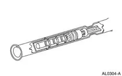
The evaporator core orifice has the following characteristics:
- It is located in the A/C condenser to evaporator line.
- It has filter screens located on the inlet and outlet ends of the tube body.
- The inlet filter screen acts as a strainer for the liquid refrigerant flowing through the evaporator core orifice.
- O-ring seals on the evaporator core orifice prevent the high-pressure liquid refrigerant from bypassing the evaporator core orifice.
- Adjustment or repair cannot be made to the evaporator core orifice assembly. A new evaporator core orifice must be installed as a unit.
 Refrigerant Lines
The condenser to evaporator tube (19835) contains the high pressure liquid
refrigerant upstream of the
evaporator core orifice.
The A/C manifold and tube (19D734) is attached to the A/C compressor, ...
 Suction Accumulator
NOTE: Installation of a new suction accumulator is not required when
repairing the air conditioning
system except when there is physical evidence of contamination from a failed A/C
compres ...
Other materials:
Rear Drive Axle and Differential
The differential housing (4010) consists of a cast aluminum housing and
a cast aluminum
differential housing cover (4033). The differential housing cover uses
silicone sealant as a
gasket.
The hypoid-design gearset consists of a 8.8-inch ...
Key Programming - Program a Key Using Two
Programmed Keys
Special Tool(s)
Worldwide Diagnostic System
(WDS)
418-F224,
New Generation STAR (NGS)
Tester
418-F052, or equivalent
diagnostic tool
NOTE: This procedure only works if two or more programmed ignition keys are
available and it is
desi ...
Installation
1. Position the wiring harness:
Install the wiring harness retainer onto the LH valve cover stud bolt.
Install the wiring harness retainer into the power steering reservoir.
2. Connect the ECT sensor electrical connector.
3. Connect the CMP senso ...
