Ford Mustang (1999-2004) Service Manual: Clutch Pedal - Quadrant and Pawl Assembly
Removal
1. Disconnect the battery ground cable (14301).
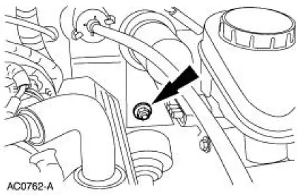
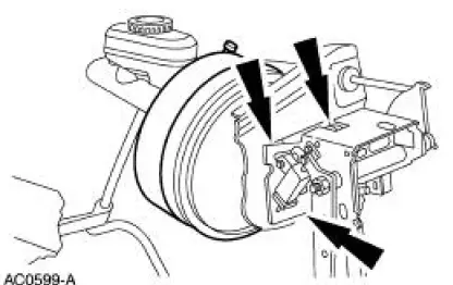
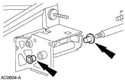
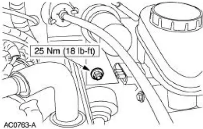
2. Loosen the nut from inside the engine compartment.
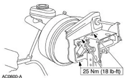
3. Loosen the nuts from inside the vehicle.
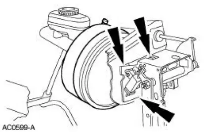
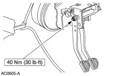
4. Loosen the screw.
5. Disconnect the brake pedal position (BPP) switch electrical connector.
6. Disconnect the brake pedal-to-power brake booster push rod.
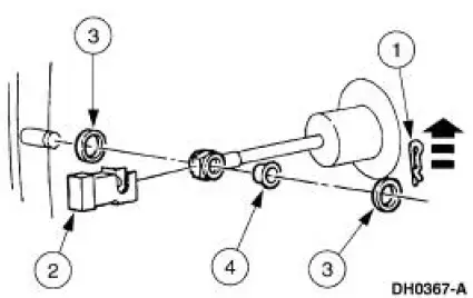
1. Remove the self-locking pin.
2. Remove the BPP switch from the brake master cylinder push rod.
3. Remove the brake master cylinder push rod spacers (2B129).
4. Remove the brake master cylinder push rod bushing (2474).
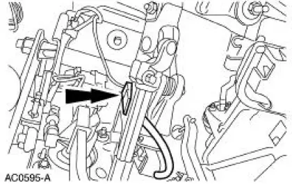
7. Disconnect the clutch pedal position (CPP) switch electrical connector.
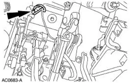
8. Disconnect the deactivation switch connector from the wiring harness.
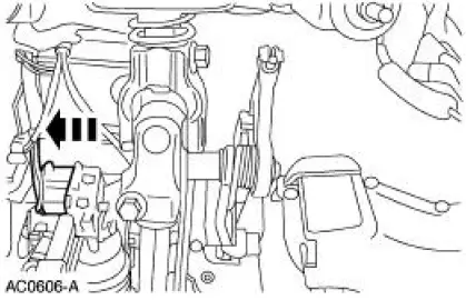
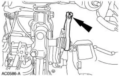
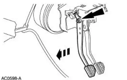
9. WARNING: Do not allow the quadrant to snap rearward. Failure to follow this instruction may result in personal injury.
NOTE: Lift the clutch pedal all the way up to release the clutch release lever cable (7K553).
Rotate the clutch pedal adjuster quandrant (7L583) and unhook the clutch release lever cable (7K553).
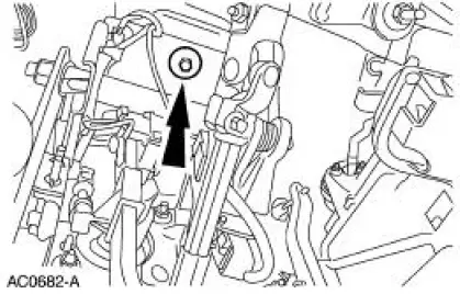
10. Remove the nuts.
11. Remove the screw.
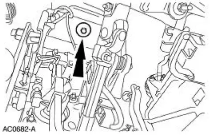
12. Remove the nut and the clutch pedal (7519).
13. Remove the self-adjusting mechanism.
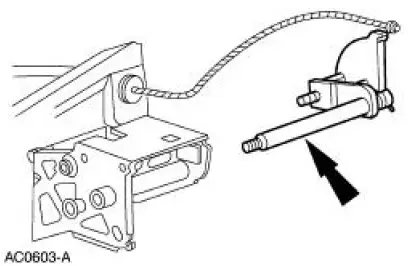
14. Remove the self-adjusting mechanism shaft bushings.
Installation
1. NOTE: Before the installation of the clutch pedal shaft or clutch pedal, remove and inspect the brake and clutch pedal bushings. Clean and lubricate with a light film of engine oil meeting Ford specification WSS-M2C153-G and replace the brake and clutch pedal bushing if excessive wear is evident.
To install, reverse the removal procedure.
 Clutch Controls (Description and Operation)
The clutch control system engages and disengages the clutch. The clutch
control system disengages
the clutch when the clutch pedal is depressed and engages the clutch when the
clutch pe ...
 Release Cable - Clutch
Removal
CAUTION: Whenever the clutch release lever cable (7K553) is
disconnected for any
reason, such as transmission removal, clutch pedal components or clutch
release lever cable
replacement, ...
Other materials:
Instrument Cluster Self-Diagnostic Mode
To enter the instrument cluster self-diagnostic mode, press and hold the
instrument cluster
SELECT/RESET button, turn the ignition switch to the RUN position, and then
continue pressing the
SELECT/RESET button (five seconds) until tESt is displayed in th ...
General information
Radio Frequencies and Reception Factors
AM and FM frequencies are established by the Federal Communications
Commission (FCC) and the Canadian Radio and Telecommunications
Commission (CRTC). Those frequencies are:
AM: 530, 540–1700, 1710 kHz
FM: 87.9–107.7, ...
Pinpoint Test O: DTC B1870 - Air Bag Indicator Shorted to Battery
Normal Operation
The air bag indicator is designed to illuminate for 6 (+/-2) seconds
when the ignition switch is turned to
the RUN position. This initial 6 seconds of illumination is considered
normal operation and is called
proveout of the air ba ...
