Ford Mustang (1999-2004) Service Manual: Removal
CAUTION: Suspension fasteners are critical parts because they affect performance of vital components and systems and their failure can result in major service expense. A new part with the same part number must be installed if installation becomes necessary. If substitution is necessary, the part must be of the same finish and property class. Torque values must be used as specified during reassembly to make sure of correct retention of these parts.
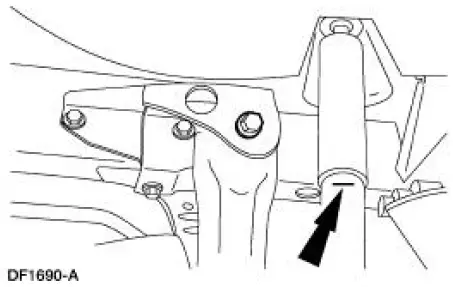
1. Mark the rear shock absorber (18125) relative to the protective sleeve with the vehicle in a static, level ground position (curb height).
2. Raise the vehicle on a hoist. .
3. Remove both wheel and tire assemblies.
4. Remove the rear brake disc.
5. Remove the rear springs (5560). For additional information, refer to Spring-Cobra in this section.
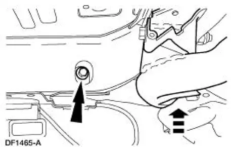
6. Raise the subframe into position and remove the front bolts.
7. Lower the subframe from the vehicle.
8. Mark the cam bolt position relative to the upper suspension arm and bushing (5500).
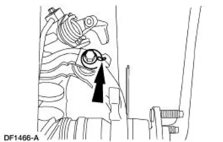
9. NOTE: Mark a new cam bolt in the same position as the old one for assembly reference before discarding the old bolt.
Disconnect the upper suspension arm and bushing from the knuckle (5A968/5A969).
1. Remove and discard the nut and bolt.
2. Disconnect the upper suspension arm and bushing.
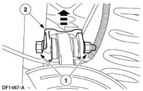
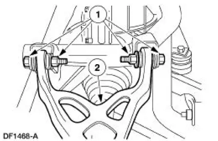
10. Remove the upper suspension arm and bushing.
1. Remove and discard the nuts and bolts.
2. Remove the upper suspension arm and bushing.

 Installation
CAUTION: The upper suspension arm and bushing nuts must be tightened
with the
suspension at curb height. Failure to do so can result in bushing failure,
resulting in poor ride
and handling.
NOTE: If ...
Other materials:
Actuator - Door Lock
Removal
1. Remove the door trim panel (23942). For additional information,
refer to Section.
2. Remove the door latch (21812). For additional information, refer to
Latch-Door .
3. Remove the door ajar switch.
Release the locking tab.
4 ...
Actuator Cable - Speed Control-Cobra
1. Remove the speed control actuator cable end from the throttle body.
1. Lift the speed control cable from the throttle nailhead.
2. Release the speed control cable from the throttle bracket.
2. Remove the speed control cable from the retaining cli ...
Lifting
CAUTION: Do not allow the lift adapters to contact the steering
linkage, suspension arms,
stabilizer arms, or to compress the lower suspension arm stabilizer bar
insulator (5493).
Damage to the suspension, exhaust and steering linkage components may occur i ...
