Ford Mustang (1999-2004) Service Manual: Installation
CAUTION: The upper suspension arm and bushing nuts must be tightened with the suspension at curb height. Failure to do so can result in bushing failure, resulting in poor ride and handling.
NOTE: If installing a new upper suspension arm and bushing, mark the cam bolt side of the new arm in the same position as the old arm for assembly reference.
1. Install the upper suspension arm and bushing.
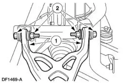
1. Position the arm and bushing on the subframe.
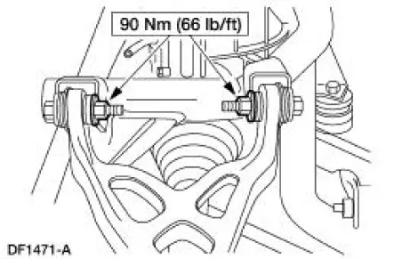
2. Install new bolts and nuts. Do not tighten the nuts at this time.
2. Connect the upper suspension arm and bushing to the knuckle.
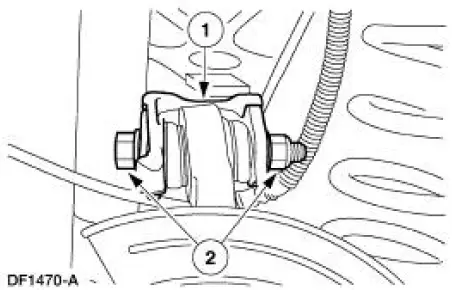
1. Position the arm and bushing.
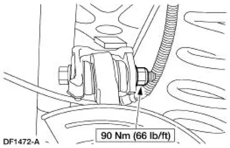
2. Install a new cam bolt and a new nut. Do not tighten the nut at this time.
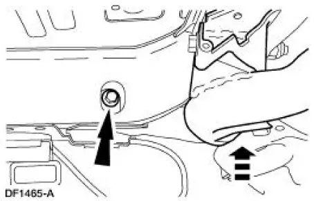
3. Raise the subframe into position and install new front bolts.
4. Install the springs. For additional information, refer to Spring-Cobra in this section.
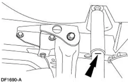
5. Position a jack stand under the lower suspension arm and bushing.
6. Raise the suspension until the shock absorber is compressed to the alignment mark (curb height).
7. Tighten the nuts.
8. Position the cam bolt so the marks are aligned. Tighten the nut.
9. Lower the suspension and remove the jack stand.
10. Install the rear brake disc.
11. Install the wheel and tire assembly.
12. Lower the vehicle.
13. Check wheel alignment, adjust if necessary.
 Removal
CAUTION: Suspension fasteners are critical parts because they affect
performance of vital
components and systems and their failure can result in major service expense. A
new part with
the same part ...
 Lower Arm
Removal
CAUTION: Suspension fasteners are critical parts because they affect
performance of vital
components and systems and their failure can result in major service expense. A
new part with
the sa ...
Other materials:
Child Safety
GENERAL INFORMATION
See the following sections for directions on how to properly use safety
restraints for children.
WARNING: Always make sure your child is secured properly in
a device that is appropriate for their height, age and weight.
Child safety restra ...
Ordering additional owner’s literature
To order the publications in this portfolio, contact Helm, Incorporated at:
HELM, INCORPORATED
47911 Halyard Drive
Plymouth, Michigan 48170
Attention: Customer Service
Or to order a free publication catalog, call toll free: 1-800-782-4356
Monday-Friday 8:00 a. ...
Cleaning the exterior
Wash your vehicle regularly with cool or lukewarm water and a neutral
pH shampoo, such as Motorcraft® Detail Wash.
• Do not use a commercial or high-pressure wand on the surface or
edge of stripes and graphics. This can cause damage to the film and
cause th ...
