Ford Mustang (1999-2004) Service Manual: Removal
1. Remove the differential housing cover (4033) and drain the rear axle (4001). For additional information, refer to Differential Housing Cover in this section.
2. CAUTION: Reinstall the differential pinion shaft (4211) and the bolt in the differential case (4204) after removing the axle shafts (4234).
Remove the axle shafts. For additional information, refer to Axle Shaft in this section.
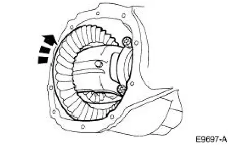
3. Wipe the lubricant from the internal working parts and inspect the parts for wear and damage.
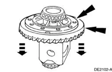
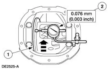
4. Rotate the differential assembly to check for roughness indicating bearing/gear damage.
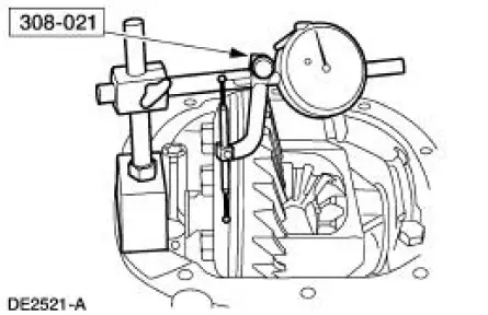
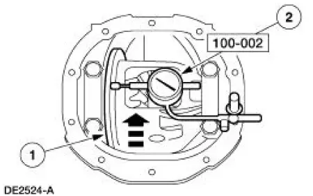
5. Using a suitable dial indicator and the special tool, measure and note the ring gear backface runout.
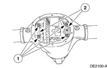
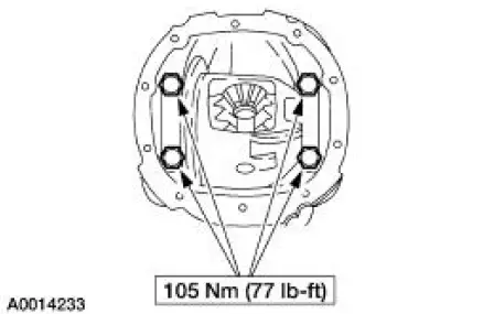
6. CAUTION: Mark the position and location of the bearing caps, as the arrows may not be visible. Always install the bearing caps in their identical locations and positions.
Remove the bearing caps.
1. Remove the bolts.
2. Remove the bearing caps.
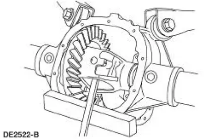
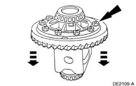
7. WARNING: Do not allow the differential assembly to fall. Failure to follow these instructions may result in personal injury and component damage.
CAUTION: Place a wood block between the pry bar and the differential housing 4010) to protect the machined surface from damage.
Using a pry bar and a wood block, remove the differential assembly from the differential housing.
8. Remove the 10 bolts.
9. CAUTION: Do not damage the threads in the bolt holes.
Insert a punch in the bolt holes, and drive off the ring gear.
10. If the ring gear backface runout measurement, taken at the beginning of this procedure, did not exceed the specification, proceed to the appropriate procedure as necessary: Drive Pinion , Differential Case and Ring Gear-Conventional or Differential Case and Ring Gear-Traction- Lok in this section, or to Installation in this procedure. If the ring gear backface runout measurement, taken at the beginning of this procedure, exceeded the specification, the cause may be a warped ring gear, differential case/differential bearing damage. Proceed as follows to verify the cause of the excessive runout.
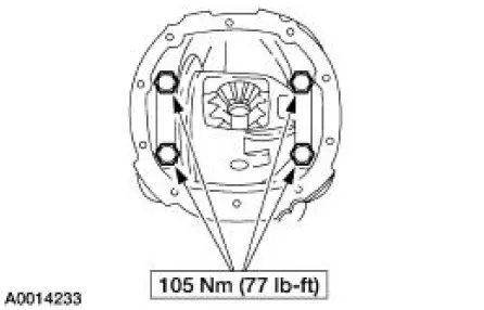
11. Position the differential assembly, including the differential bearing cups (4222) and differential bearing shims (4067), in the differential housing. Install the bearing caps and bolts.
12. Position the special tool.
1. Rotate the differential case to verify that the differential bearings (4221) have seated correctly.
2. Position the special tool.
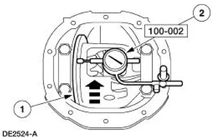
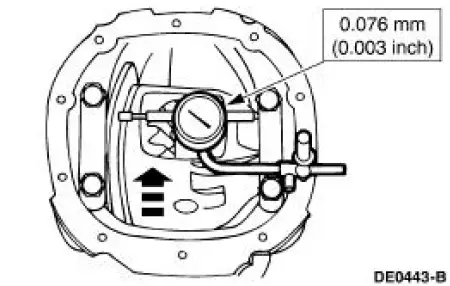
13. Measure and note the differential case runout.
1. Rotate the differential case.
2. Note the runout.
- If the runout does not exceed the specification, install a new ring gear and drive pinion gear. For additional information, refer to Drive Pinion in this section and to Installation in this procedure.
- If the runout exceeds the specification, the ring gear is true and the concern is due to either differential case/differential bearing damage. Proceed as follows.
14. Remove the differential assembly from the differential housing.
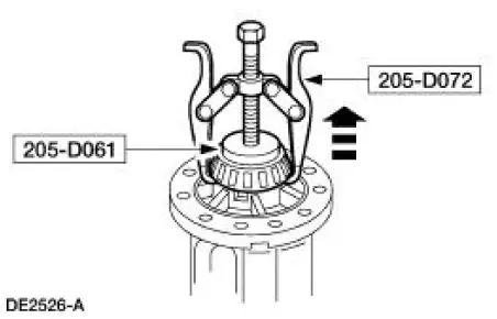
15. Using the special tools, remove the differential bearings.
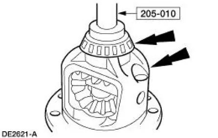
16. Using the special tool, install the new differential bearings.
17. Position the differential assembly, including the differential bearing cups and differential bearing shims, in the differential housing. Install the bearing caps and bolts.
18. Position the special tool.
1. Rotate the differential case to verify that the differential bearings have seated correctly.
2. Position the special tool.
19. Measure the differential case runout.
- If the runout does not exceed the specification, use the new differential bearings for assembly.
- If the runout exceeds the specification, install a new differential case. For additional information, refer to Differential Case and Ring Gear-Conventional or Differential Case and Ring Gear-Traction-Lok in this section.
20. Remove the differential assembly from the differential housing.
 Differential Case
Special Tool(s)
2-Jaw Puller
205-D072 (D97L-4221-A) or
equivalent
Dial Indicator Gauge with
Holding Fixture
100-002 (TOOL-4201-C) or
equivalent
Gauge, Clutch Hou ...
 Installation
All axles
1. Position the ring gear and the differential case. Align the bolt holes by
starting two bolts through
the holes in the differential case and the ring gear. Press the ring gear on the
dif ...
Other materials:
Manual Transmission
The T5OD 5-speed transmission:
fifth speed gear functions as an overdrive gear.
forward gears are synchronized and helical cut.
shift interlock system prevents the engagement of more than one
gear.
Transmission, Manual Five-Speed
T ...
Introduction
ABOUT THIS MANUAL
Thank you for choosing Ford. We recommend that you take some time
to get to know your vehicle by reading this manual. The more that you
know about it, the greater the safety and pleasure you will get from
driving it.
WARNING: Always drive wit ...
Using voice recognition
This system helps you control many features using voice commands.
This allows you to keep your hands on the wheel and focus on what is in
front of you.
Initiating a Voice Session
Push the voice icon; a tone sounds and Listening appears in the
display. Say an ...
