Ford Mustang (1999-2004) Service Manual: Removal
1. Disconnect the battery ground cable.
2. Remove the air cleaner outlet pipe.
3. Remove the radiator sight shield.
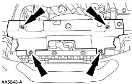
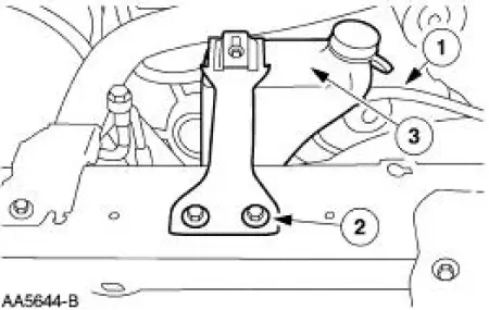
4. Remove the coolant recovery reservoir.
1. Disconnect the hose.
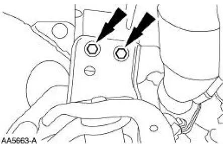
2. Remove the bolts.
3. Remove the coolant recovery reservoir.
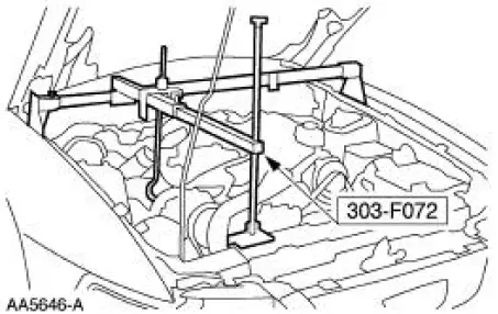
5. Install the special tool.
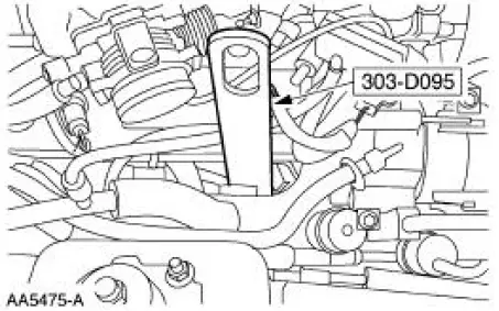
6. Install the special tool.
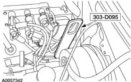
7. Install the special tool.
8. Raise and support the vehicle.
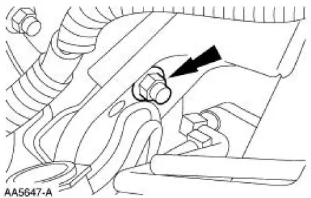
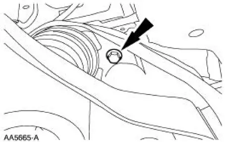
9. Remove the LH engine mount nut.
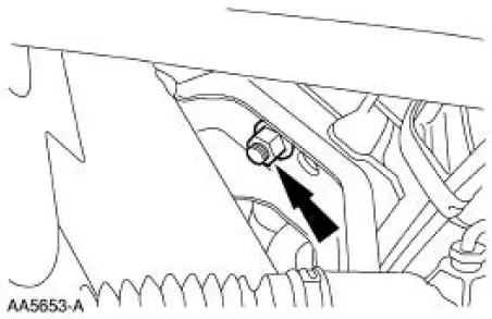
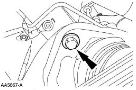
10. Remove the RH engine mount nut.
11. Lower the vehicle.
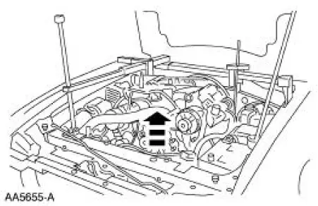
12. Raise the engine.
13. Raise and support the vehicle.
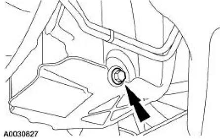
14. Remove the oil pan drain plug and drain the engine oil.
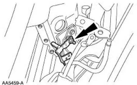
15. Remove the starter motor.
16. Position the wiring harness bracket aside.
17. Remove the transmission lower bolts.

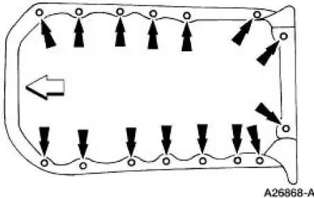
18. Remove the oil pan bolts.
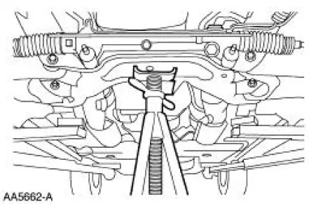
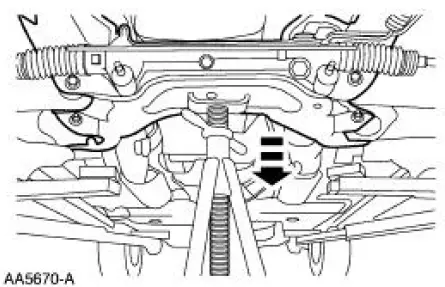
19. Position a safety stand under the subframe crossmember.
20. Remove the four subframe lower bolts.
21. Remove the two subframe upper bolts.
22. NOTE: Do not completely remove these bolts.
Loosen the two bolts.
23. Lower the front subframe.
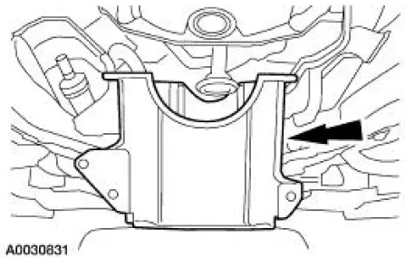
24. Remove the oil pan.
 Oil Pan
Special Tool(s)
3 Bar Engine Support Kit
303-F072
Lifting Bracket Set, Engine
303-D095 (D94L-6001-A) or
equivalent
Material
...
 Installation
1. NOTE: If the oil pan is not secured within four minutes, the
sealant must be removed and the
sealing area cleaned with metal surface cleaner. Allow to dry until there is
no sign of wetness,
o ...
Other materials:
Hydraulic Control Unit
Removal
1. Disconnect the battery ground cable(14301).
2. Disconnect the anti-lock-brake control module electrical connector.
3. NOTE: The 4 wheel anti-lock brake system (4WABS) with traction
control is shown , the
4WABS without traction control system is ...
Removal
1. Remove the nuts and position the radio ignition interference capacitors
aside.
2. Remove the valve covers. For additional information, refer to Valve Cover
RH and Valve Cover
LH in this section.
3. Remove the cooling fan.
4. Remove the accessory drive ...
Removal
1. Remove the roller followers. For additional information, refer to Roller
Followers in this section.
2. Remove the spark plugs. For additional information, refer to Section .
3. Position the piston of the cylinder being serviced at the bottom of the
stro ...
