Ford Mustang (1999-2004) Service Manual: Removal
1. Remove the air intake scoop bracket. For additonal information, refer to Section.
2. Remove the air cleaner outlet tube. For additional information, refer to Section.
3. Disconnect the accelerator cable, the speed control actuator cable and the return spring.
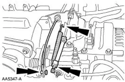
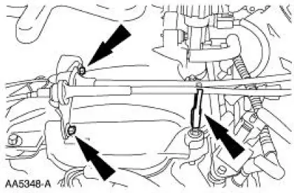
4. Remove the bolts, disconnect the clip and position the cables out of the way.
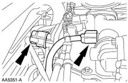
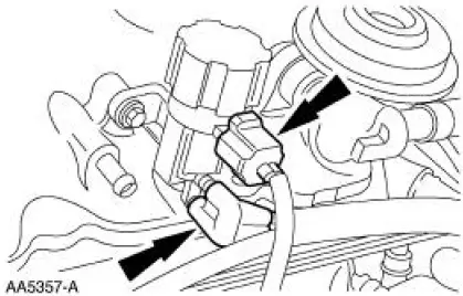
5. Disconnect the throttle position (TP) sensor.
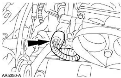
6. Disconnect the evaporative emissions (EVAP) return hose.
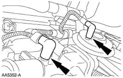
7. Disconnect the idle air control valve and the differential pressure feedback EGR.
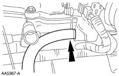
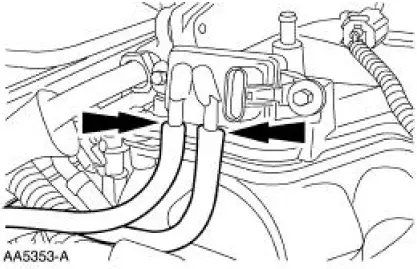
8. Disconnect the main chassis vacuum supply line and the EGR valve vacuum line.
9. Disconnect the differential pressure feedback EGR hoses.
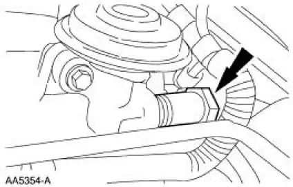
10. Disconnect the EGR valve to exhaust manifold tube from the EGR valve.
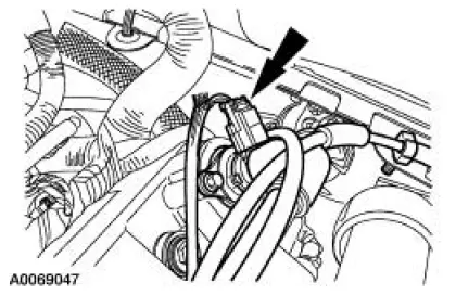
11. Disconnect the electrical connector and the vacuum lines from the EGR vacuum regulator solenoid.
12. Remove the PCV valve-to-intake manifold tube.
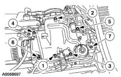
13. Remove the upper intake manifold bolts in the sequence shown and remove the intake manifold assembly.
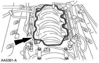
14. Inspect and clean the sealing surfaces.

 Installation
1. Install the upper intake manifold gasket.
2. Install the intake manifold and bolts in the sequence shown.
3. Install the PCV valve-to-intake manifold tube.
4. Connect the vacuum hoses and ...
Other materials:
Pinpoint Test B: LFC 21/DTC B1921 - RCM Bracket Ground Resistance High
Normal Operation
WARNING: The tightening torque of the restraints control module
(RCM) retaining bolts is
critical for proper air bag supplemental restraint system (SRS)
operation. Refer to Restraints
Control Module (RCM) in this section for correc ...
NVH Condition and Symptom Categories
A good diagnostic process is a logical sequence of steps that lead to the
identification of a causal
system. Use the condition and symptom categories as follows:
Identify the operating condition that the vehicle is exhibiting.
Match the operating condition ...
Installation
Using special tool 205-054
NOTE: This is the preferred method for installing the pinion bearing
cups. If necessary, proceed to
Using special tools 205-153, 205-054, and 205-D055 in this procedure for an
alternate method.
1. Position the special tools and th ...
