Ford Mustang (1999-2004) Service Manual: Installation
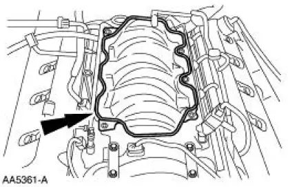
1. Install the upper intake manifold gasket.
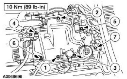
2. Install the intake manifold and bolts in the sequence shown.
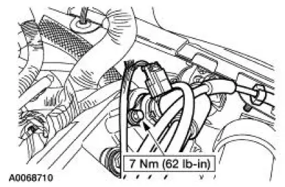
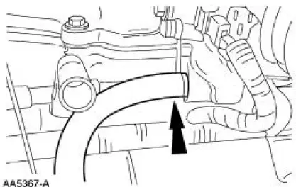
3. Install the PCV valve-to-intake manifold tube.
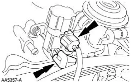
4. Connect the vacuum hoses and the electrical connector to the EGR vacuum regulator solenoid.
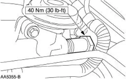
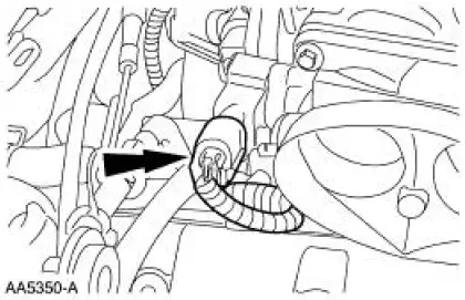
5. Connect the EGR tube to the EGR valve.
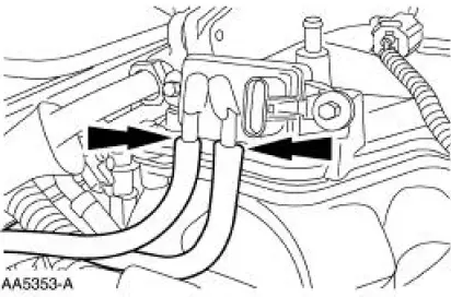
6. Connect the hoses to the differential pressure feedback EGR.
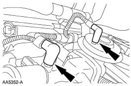
7. Connect the main chassis vacuum supply line and the EGR valve vacuum line.
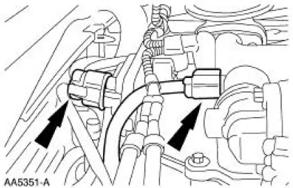
8. Connect the IAC valve and the differential pressure feedback EGR electrical connectors.
9. Connect the EVAP return hose.
10. Connect the TP sensor.
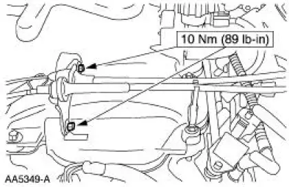
11. Position the cables and bracket.
- Install the bolts, connect the clip.
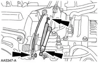
12. Connect the throttle cable, the speed control actuator cable and throttle return spring.
13. Install the air cleaner outlet tube. For additional information, refer to Section.
14. Install the air intake scoop bracket. For additional information, refer to Section .
 Removal
1. Remove the air intake scoop bracket. For additonal information, refer to
Section.
2. Remove the air cleaner outlet tube. For additional information, refer to
Section.
3. Disconnect the accelera ...
 Intake Manifold - Lower
Material
Item
Specification
Metal Surface Cleaner
F4AZ-19A536-RA or equivalent
WSE-M5B392-A
...
Other materials:
Inspection and Verification
1. Verify the customer concern by operating the engine to duplicate the
condition.
2. Visually inspect for obvious signs of mechanical damage. Refer to the
following chart.
Visual Inspection Chart
Mechanical
Engine coolant leaks
...
Moulding - Roof Side
Removal and Installation
1. Remove the weatherstrip.
2. Remove the exterior roof side moulding screws.
3. Remove the interior roof side moulding screws.
4. Remove the roof side moulding screw.
5. Release the clips.
1. Lift up to release the two ...
Vibration When Brakes are Applied
For vibration concerns when brakes are applied, perform the following
procedure.
Visually inspect:
tire condition and pressure.
suspension bushings and ball joints.
Correct as necessary.
1. Verify and isolate the concern. Brake roughness can be felt in: ...
