Ford Mustang (1999-2004) Service Manual: Removal
CAUTION: Since the engine is not free-wheeling, if the crankshaft or the camshafts are moved in any manner during removal and installation, the crankshaft and the camshafts must be re-synchronized.
1. Remove the engine front cover. For additional information, refer to Engine Front Cover in this section.
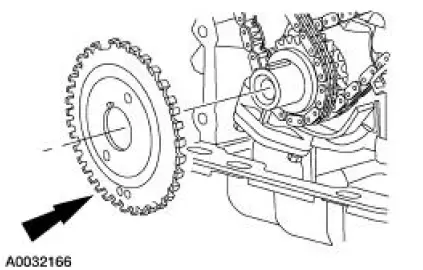
2. Remove the crankshaft sensor ring from the crankshaft.
3. CAUTION: Unless otherwise instructed, at no time when the timing chains are removed and the cylinder heads are installed is the crankshaft or the camshaft to be rotated. Severe piston and valve damage will occur.
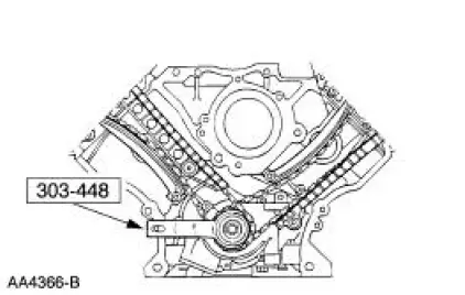
Using the special tool, position the crankshaft as shown.
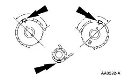
4. CAUTION: The camshaft timing marks must be correctly lined up or damage to the valves and pistons can occur.
NOTE: The copper links on the timing chain may not line up with the timing marks on the sprockets.
Make sure the timing marks on the camshaft sprockets are correctly positioned. If necessary, turn the crankshaft one full turn clockwise to correctly position the sprockets.
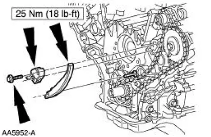
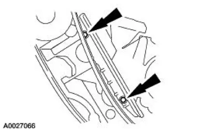
5. NOTE: LH shown; RH similar.
Remove the two bolts, the timing chain tensioner and tensioner arm.
6. CAUTION: Unless otherwise instructed, at no time when the timing chains are removed and the cylinder heads are installed is the crankshaft or the camshaft to be rotated. Severe piston and valve damage will occur.
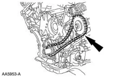
Remove the LH and RH timing chains and the crankshaft sprocket.
Remove the special tool from the crankshaft.
- Remove the RH timing chain from camshaft sprocket.
- Remove the RH timing chain from the crankshaft sprocket.
- Remove the LH timing chain from the camshaft sprocket.
- Remove the LH timing chain and the crankshaft sprocket.
7. CAUTION: The bolts are different lengths and must be returned to their original location.
NOTE: RH shown; LH similar.
Remove the bolts and the timing chain guides.
 Timing Drive Components
Special Tool(s)
Holding Tool, Crankshaft
303-448 (T93P-6303-A)
...
 Installation
1. CAUTION: Timing chain procedures must be followed exactly or damage
to the
pistons or valves will result.
Compress the tensioner plunger, using a soft-jawed vise.
2. Install a retaining clip on ...
Other materials:
Differential Case and Ring Gear - Traction-Lok
Special Tool(s)
2-Jaw Puller
205-D072 (D97L-4221-A) or
equivalent
Gauge, Differential Clutch
205-022 (T66L-4204-A)
Gauge, Differential Clutch
205-135 (T80P-4946-A)
Installer, Differential Side
Bearing
205-010 (T57 ...
Crankshaft Rear Oil Seal
Special Tool(s)
Installer, Crankshaft Rear Oil
Seal
303-518 (T95P-6701-DH)
Remover, Crankshaft Rear Oil
Seal
303-519 (T95P-6701-EH)
Installer, Crankshaft Rear Oil
Seal
303-516 (T95P-6701-BH)
Remover ...
Release Cable - Clutch
Removal
CAUTION: Whenever the clutch release lever cable (7K553) is
disconnected for any
reason, such as transmission removal, clutch pedal components or clutch
release lever cable
replacement, it is imperative the correct method for installing the clut ...
