Ford Mustang (1999-2004) Service Manual: Reservoir
Removal
WARNING: Brake fluid contains polyglycol ethers and polyglycols. Avoid contact with eyes. Wash hands thoroughly after handling. If brake fluid contacts eyes, flush eyes with running water for 15 minutes. Get medical attention if irritation persists. If taken internally, drink water and induce vomiting. Get medical attention immediately.
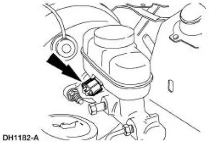
1. Disconnect the brake master cylinder fluid level switch.
2. Use a suitable suction device to drain the brake master cylinder reservoir (2K478).
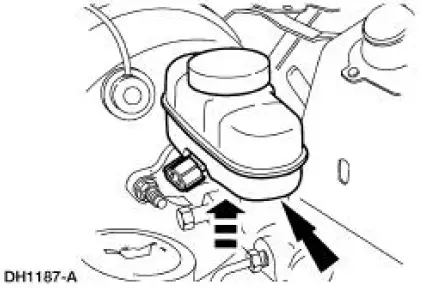
3. Carefully pry up on the brake master cylinder reservoir and remove.
Installation
1. NOTE: Whenever installing a new brake master cylinder reservoir, install new grommets.
Install the brake master cylinder reservoir.
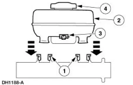
1. Lubricate the two grommets with High Performance DOT 3 Brake Fluid C6AZ-19542-AB or equivalent fluid meeting Ford specification ESA-M6C25-A and insert the grommets into the brake master cylinder (2140).
2. Press the brake master cylinder reservoir into the grommets until it is fully seated.
3. Connect the brake master cylinder fluid level switch.
4. Fill the brake master cylinder reservoir with clean High Performance DOT 3 Brake Fluid C6AZ-19542-AB or equivalent fluid meeting Ford specification ESA-M6C25-A.
5. Bleed the brake master cylinder.
 Master Cylinder - Hydro-Boost
Removal
1. Disconnect the fluid level sensor connector.
2. Disconnect the brake tubes.
3. Remove the brake master cylinder nuts.
4. Remove the brake master cylinder (2140).
Installation
1. T ...
 Control Valve
Removal
1. Disconnect the brake tubes.
2. Remove the brake fluid control valve bracket nut.
Installation
1. To install, reverse the removal procedure.
...
Other materials:
Gear (Disassembly and Assembly)
Special Tool(s)
Head Mounting Fixture
303-D041 (D83L-500-B1) or
Equivalent
Inner Tie Rod Socket Tool
211-D025 (D90P-3290-A) or
Equivalent
Steering Gear Holding Fixture
211-D011 (D87P-3504-B) or
Equivalent
Material
...
Range Selection
The transmission has six range positions: P, R, N, (D), 2 and 1.
Park
In the PARK position:
there is no powerflow through the transmission.
the parking pawl locks the output shaft to the case.
the engine can be started.
the ignition key can ...
Tracer Dye Leak Detection
Special Tool(s)
120 Watt 110 Volt UV Lamp
20C
164-R0721 or equivalent
NOTE: Ford Motor Company vehicles are produced with a permanent leak
tracer dye incorporated into
the A/C system. The location of leaks can be pinpointed by the bright
ye ...
