Ford Mustang (1999-2004) Service Manual: Hydraulic Brake Actuation
Torque Specifications
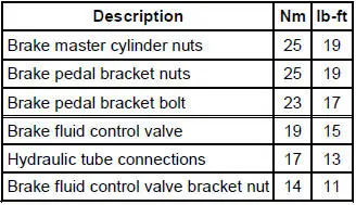
- Hydraulic Brake Actuation (Description and Operation)
- Pedal and Bracket
- Master Cylinder
- Master Cylinder - Hydro-Boost
- Reservoir
- Control Valve
 Cable and Conduit
Removal
NOTE: The RH rear is shown, the LH is similar.
1. CAUTION: If any component in the parking brake system requires
repair or if the
rear axle housing (4010) is removed, the cable tension mu ...
 Hydraulic Brake Actuation (Description and Operation)
CAUTION: Blistering or swelling of rubber brake components may indicate
contamination
of the brake fluid by a petroleum based substance. New rubber components must be
installed
in the hydr ...
Other materials:
Supercharger Cooling (Description and Operation)
CAUTION: Some vehicle cooling systems are filled with Motorcraft
Premium Engine
Coolant VC-4-A (in Oregon VC-5, in Canada CXC-10) or equivalent meeting Ford
specification
ESE-M97B44-A (green color). Others are filled with Motorcraft Premium Gold
Engine Cool ...
Installation
LH mount
1. Position the engine mount and install the bolt and studbolts.
2. Attach the ground cables and install the nuts.
RH mount
3. Position the engine mount and install the bolts and studbolt.
4. Attach the wiring harness and install the nut.
Both ...
Spring Codes
The spring code portion of the vehicle certification (VC) label identifies
both the front and rear springs.
The first letter/number indicates the front spring code. The second
letter/number indicates the rear
spring code.
Front springs - base part numbe ...
