Ford Mustang (1999-2004) Service Manual: Shift Point Road Test
This test verifies that the shift control system is operating correctly.
1. Bring engine and transmission up to normal operating temperature.
2. Operate vehicle with transmission range selector lever in (D) position.
3. NOTE: Shift speed ranges are approximate for all applications. For specific applications (engine, axle ratio and application) refer to the Automatic Transmission Specification Issue, available from Ford Customer Service Division.
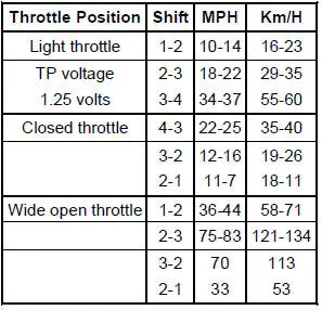
Apply minimum throttle and observe speeds at which upshift occurs and torque converter engages; refer to the 4R70W Shift Speeds chart in this section.
4. With the transmission in Overdrive (fourth gear), press the transmission control switch. The transmission should downshift to third gear. Release the accelerator pedal; engine braking should occur.
5. Press accelerator pedal to floor, wide open throttle (WOT). Transmission should shift from third to second gear, or third to first, depending on vehicle speed. Torque converter clutch should disengage and then reapply.
6. With the transmission in (D) position and speed above 80 km/h (50 mph) and less than half throttle, move the transmission range selector lever from (D) position to manual 2 position and remove pressure from the accelerator pedal. Transmission should immediately downshift into second gear. With vehicle remaining in manual 2 position, move the transmission range selector lever into manual 1 position, and release accelerator pedal. Transmission should downshift into first gear at speeds approximately below 45-56 km/h (28-35 mph).
7. If transmission fails to upshift/downshift or torque converter clutch does not apply and release, refer to Diagnosis By Symptom in this section.
Shift Speeds 4.6L 4V MACH 1 (3.55:1 Axle Ratio)
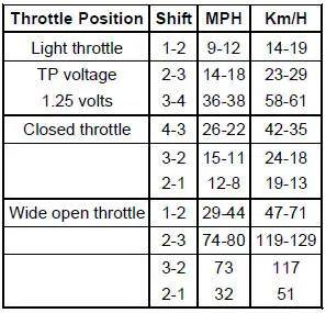
Shift Speeds 4.6L 2V HO (3:27:1 Axle Ratio)
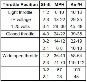
Shift Speeds 3.8L (3:27:1 Axle Ratio)
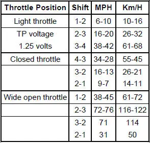
Shift Speeds 3.8L (3:08:1 Axle Ratio)
 Preliminary Inspection
The following items must be checked prior to beginning the diagnostic
procedures:
Know and Understand the Concern
In order to correctly diagnose a concern, first understand the
customer compla ...
 Torque Converter Diagnosis
Prior to the installation of a new or remanufactured torque
converter, all diagnostic procedures must be
followed. This is to prevent the unnecessary installation of torque
converters. Only af ...
Other materials:
Knob
Removal
1. Remove the shifter top control panel.
2. Disconnect the electrical connectors.
3. Remove the shifter bezel.
4. Remove the bulb from the bezel.
5. Disconnect the TCS connector.
6. CAUTION: Extra force may be needed to lift up on the handle. Do ...
Rear seats
Rear Seat Entry and Exit
Use the seatback release to fold the
back of the front seat forward for
rear seat access. This release handle
is located on the upper back of the
front seat. The seatback locks
automatically when returned to the
normal position.
Use ...
Interior mirror
WARNING: Do not adjust the mirror when your vehicle is
moving.
Note: Do not clean the housing or glass of any mirror with harsh
abrasives, fuel or other petroleum or ammonia based cleaning products.
You can adjust the interior mirror to your preference. Some ...
