Ford Mustang (1999-2004) Service Manual: Shock Absorber
Removal
WARNING: All vehicles are equipped with gas pressurized shock absorbers which will extend unassisted. Do not apply heat or flame to the shock absorbers during removal or component servicing. Failure to follow these instructions can result in personal injury.
CAUTION: Suspension fasteners are critical parts because they affect performance of vital components and systems and their failure can result in major service expense. A new part with the same part number must be installed if installation becomes necessary. If substitution is necessary, the part must be of the same finish and property class. Torque values must be used as specified during reassembly to make sure of correct retention of these parts.
CAUTION: When using a hoist that lifts the vehicle by the frame, install new shock absorbers one at a time.
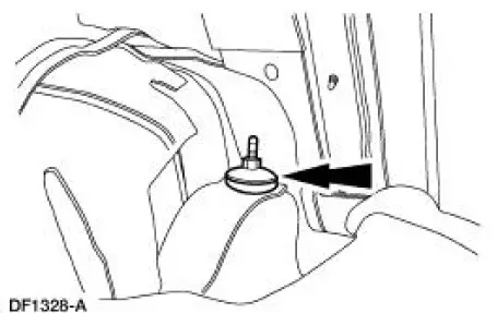
1. Open the luggage compartment lid. Position the carpet out of the way.
2. Remove and discard the retaining nut, washer and insulator assembly.
3. Raise the vehicle.
4. Remove the shock absorber (18125).
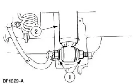
1. Remove and discard the bolt and nut.
2. Remove the shock absorber.
Installation
1. Correctly prime the new shock absorber.
2. Install a new washer and insulator on the shock absorber.
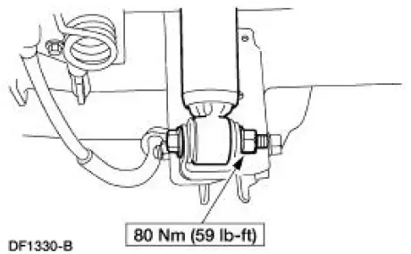
3. Position the shock absorber and install a new bolt and a new nut.
4. NOTE: When using a hoist that lifts the vehicle by the frame, have an assistant guide the shock absorber into the body while lowering the hoist.
Lower the vehicle.
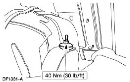
5. Install a new insulator, washer and nut.
6. Position the carpet and close the luggage compartment lid.
 Installation
1. NOTE: Inspect the spring insulators for wear or damage. Install new
spring insulators if
necessary.
Make sure the spring insulators are correctly installed on the springs.
2. Install the spring ...
 Damper
Removal
CAUTION: Suspension fasteners are critical parts because they affect
performance of vital
components and systems and their failure can result in major service expense. A
new part with
the sa ...
Other materials:
Exhaust Manifold LH
Special Tool(s)
Lifting Bracket, Engine
303-D088 (D93P-6001-A2)
Support Bar, Engine
303-290-A
Removal and Installation
1. Install the special tool.
2. Install the special tools.
3. Raise and support the vehicle. For additional ...
Countershaft Bearing
Special Tool(s)
Bearing Replacer
308-061 (T77J-7025-L)
Front Bearing Replacer
308-062 (T77J-7025-M)
Mainshaft Front Bearing
Replacer
308-081 (T82T-7003-DH)
Pinion Bearing Cone Remover
205-D002 (D79L-4621 ...
Evaporator Core Orifice
NOTE: The evaporator core orifice is an integral part of the condenser
to evaporator line and should
be installed as an assembly with the line.
NOTE: A new evaporator core orifice should be installed whenever a new
A/C compressor is installed.
The evapora ...
