Ford Mustang (1999-2004) Service Manual: Damper
Removal
CAUTION: Suspension fasteners are critical parts because they affect performance of vital components and systems and their failure can result in major service expense. A new part with the same part number must be installed if installation becomes necessary. If substitution is necessary, the part must be of the same finish and property class. Torque values must be used as specified during reassembly to make sure of correct retention of these parts.
1. Raise the vehicle.
2. Remove the wheel and tire assembly.
3. Disconnect the damper from the axle.
1. Remove the bolt.
2. Disconnect the damper.
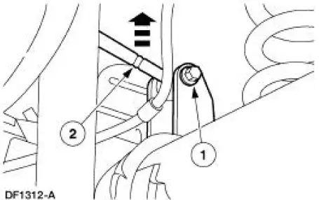
4. Remove the damper.
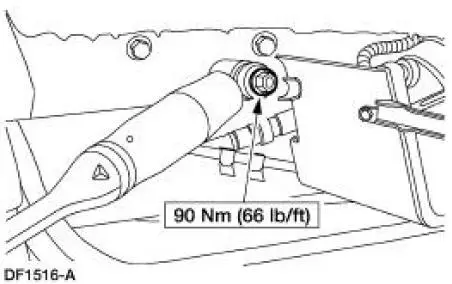
1. Remove the nut.
2. Remove the outer washer.
3. Remove the damper.
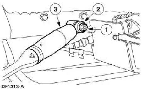
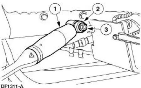
Installation
1. Make sure the inner washer is positioned on the stud.
2. Install the damper.
1. Install the damper on the rear bracket.
2. Install the outer washer.
3. Install the nut. Do not tighten the nut at this time.
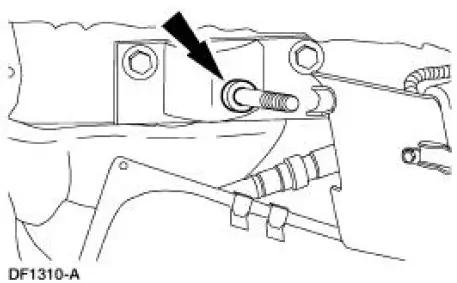
3. Connect the damper to the axle.
1. Position the damper.
2. Install the bolt.
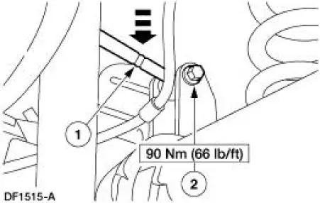
4. Tighten the nut.
5. Install the wheel and tire assembly.
6. Lower the vehicle.
 Shock Absorber
Removal
WARNING: All vehicles are equipped with gas pressurized shock absorbers
which will
extend unassisted. Do not apply heat or flame to the shock absorbers during
removal or
component servicing. ...
 Wheels and Tires
General Specifications
Torque Specifications
Description
Nm
lb-ft
Wheel nuts
129
95
...
Other materials:
Normal Schedule
The following checks or procedures should be carried out for all cars,
minivans, light trucks, sport
utilities, vans, 4x4s, natural gas and propane vehicles.
8,000 Km (5,000 Miles)
Change engine oil and install a new oil filter.
Rotate tires and inspect fo ...
Pinpoint Tests
PINPOINT TEST A: NO COMMUNICATION WITH THE INSTRUMENT
CLUSTER
Test Step
Result / Action to Take
A1 CHECK THE BATTERY POWER SUPPLY TO THE INSTRUMENT
CLUSTER
YesGO to A2 .
No
REPAIR the circuit.
TEST the system
for normal
operation.
...
Supercharger Belt Tensioner
Removal and Installation
1. Remove the supercharger drive belt cover.
2. Rotate the supercharger belt tensioner clockwise and remove the
supercharger belt.
3. Remove the bolts and the supercharger belt tensioner.
4. To install, reverse the removal proced ...
