
Ford Mustang (1999-2004) Service Manual: Geartrain
Power is transmitted from the torque converter to the Ravigneaux geartrain components through the input shaft and forward clutch cylinder.
- The geartrain contains a Ravigneaux planetary set connected by dual pinion gears.
- By holding or driving certain components of the gearset, four forward ratios and one reverse ratio are obtained and transmitted to the output shaft. The ratios are as follows:
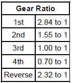
- Components of the geartrain can be held by bands or clutches and driven by clutches only.
The 4R70W uses:
- two bands.
- two one-way clutches (one roller, one mechanical diode).
- four friction clutches.
Planetary Gearset
The planetary gearset in the transmission is a Ravigneaux-type set consisting of the following components:
- forward clutch sun gear
- reverse clutch sun gear
- a pinion carrier
- long and short pinions
- output ring gear
Components are held or driven to produce forward and reverse gear ratios.
Input Shaft
The forward clutch cylinder and shaft transfers speed and torque from the converter turbine to the geartrain. This shaft is splined to the turbine on one end and to the forward clutch sun gear and stub shaft on the other end.
Stub Shaft
The stub shaft transfers power from the input shaft to the planet carrier (through the direct clutch) during third and fourth gear operation.
Output Shaft
The output shaft provides torque to the driveshaft and rear axle assembly. It is driven by the ring gear of the planetary gearset.
 Torque Converter (Description and Operation)
The torque converter transmits and multiplies torque. The torque
converter is a four-element device:
impeller assembly
turbine assembly
reactor assembly
clutch and damper assembly
...
 Apply Components
There are eight apply components used to drive or hold the planetary
gearset components.
Band-Overdrive
1. The overdrive band holds the reverse clutch drum stationary in fourth gear
an ...
Other materials:
Turn Signal and Hazard Lamps
Refer to Wiring Diagrams Cell 90 , Turn/Stop/Hazard Lamps for schematic
and connector information.
Special Tool(s)
73 III Automotive Meter
105-R0057 or equivalent
Inspection and Verification
1. Verify the customer concern.
2. Visually ins ...
Auxiliary input jack
WARNING: Driving while distracted can result in loss of vehicle
control, crash and injury. We strongly recommend that you use
extreme caution when using any device that may take your focus off
the road. Your primary responsibility is the safe operation of your ...
A/C Compressor Pressure Relief Valve
An A/C compressor pressure relief valve is incorporated into the compressor
A/C manifold and tube to:
relieve unusually high refrigerant system discharge pressure buildups.
For specifications
regarding operating pressure(s), refer to Section.
prevent ...
