Ford Mustang (1999-2004) Service Manual: Spindle
Special Tool(s)
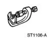 |
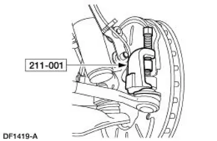
Tie-Rod End Remover 211-001 (TOOL-3290-D) or Equivalent |
Removal
CAUTION: Suspension fasteners are critical parts because they affect performance of vital components and systems and their failure can result in major service expense. A new part with the same part number or an equivalent part must be installed, if installation is necessary. Do not use a part of lesser quality or substitute design. Torque values must be used as specified during reassembly to ensure correct retention of these parts.
1. Raise the vehicle on a hoist.
2. Remove the wheel and tire assembly.
3. Remove the front wheel hub (1104). For additional information, refer to Wheel Hub and Bearing in this section.
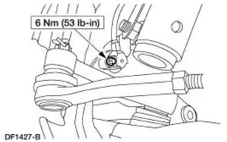
4. Remove the bolt and the ABS sensor.
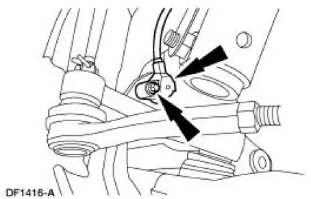
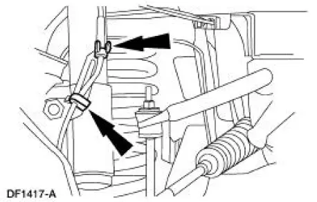
5. Unclip the ABS sensor wire from the bracket.
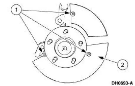
6. Remove the front brake disc shield.
1. Remove the three shield rivets.
2. Remove the shield.
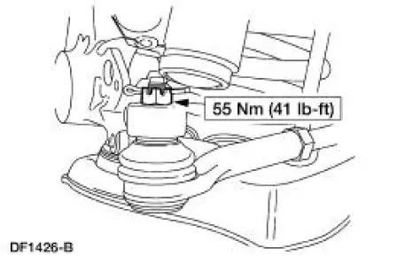
7. Remove the cotter pin and nut. Discard the cotter pin.
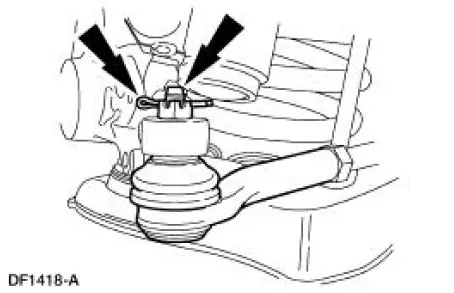
8. CAUTION: Use care not to damage the tie-rod end dust boot. Using the special tool, disconnect the tie-rod end from the front wheel spindle.
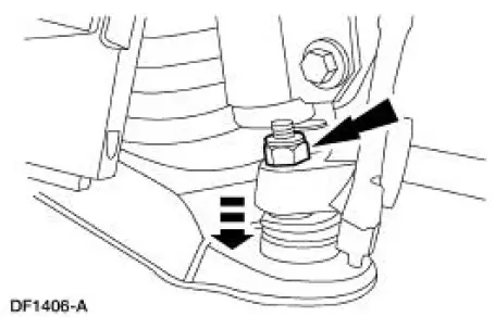
9. CAUTION: To prevent damage to the front suspension lower arm (3078), do not remove the nut from the ball joint (3050) at this time.
Disconnect the ball joint stud from the front wheel spindle (3105).
- Loosen the ball joint stud two or three turns.
- Sharply rap on the spindle at the ball joint connection to disconnect the ball joint stud.
10. Support the front suspension lower arm with a jack stand.
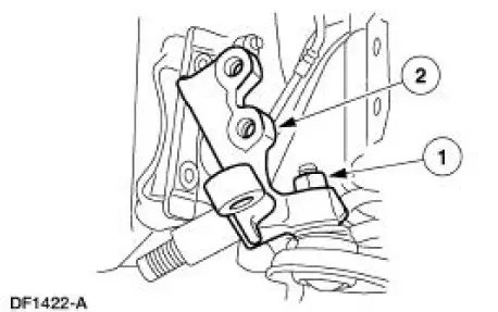
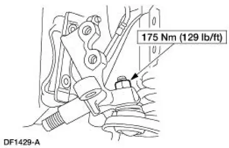
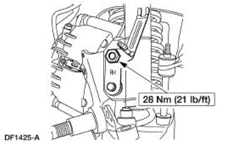
11. Remove the nut and the ABS sensor wire bracket.
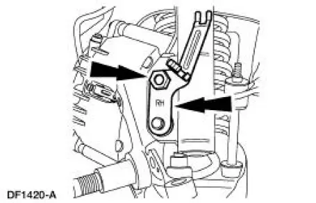
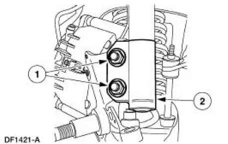
12. WARNING: All vehicles are equipped with gas pressurized shock absorbers which will extend unassisted. Do not apply heat or flame to the shock absorbers during removal or component servicing. Failure to follow these instructions can result in personal injury.
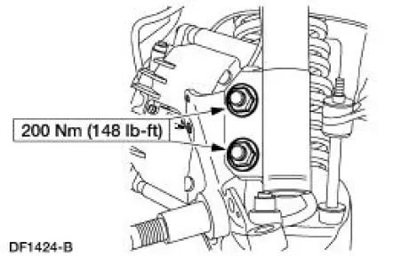
Disconnect the front shock absorber (18124) from the spindle.
1. Remove and discard the nuts and bolts.
2. Disconnect the shock absorber.
13. Remove the spindle.
1. Remove and discard the nut.
2. Remove the spindle.
Installation
1. To install, reverse the removal procedure.
2. Check wheel alignment. Adjust if necessary.
 Bushing - Stabilizer Bar
Removal
CAUTION: Suspension fasteners are critical parts because they affect
performance of vital
components and systems and their failure can result in major service expense. A
new part with
the sa ...
 Shock Absorber
Removal
WARNING: All vehicles are equipped with gas pressurized shock absorbers
which will
extend unassisted. Do not apply heat or flame to the shock absorbers during
removal or
component servicing. ...
Other materials:
HomeLink® wireless control system
WARNING: Make sure that the garage door and security device
are free from obstruction when you are programming. Do not
program the system with the vehicle in the garage.
WARNING: Do not use the system with any garage door opener
that does not have the safety s ...
USB port
WARNING: Driving while distracted can result in loss of vehicle
control, crash and injury. We strongly recommend that you use
extreme caution when using any device that may take your focus off
the road. Your primary responsibility is the safe operation of your ...
Component Tests
Brake Booster
1. Check the hydraulic brake system for leaks or insufficient fluid.
2. With the transmission (7003) in NEUTRAL, stop the engine (6007) and
apply the parking brake
control (2780). Apply the brake pedal several times to exhaust all
va ...
